Rockwell Automation 1788-FFCT NI-FBUS Configurator User Manual User Manual
Page 25
Publication 1788-UM052B-EN-P - April 2002
NI-FBUS Configurator Overview 3-5
Icons
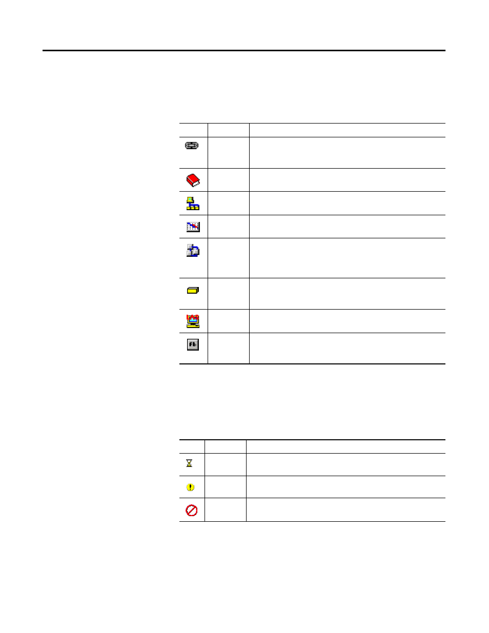
Descriptions of the project icons that appear in the Project window
follow:
State Icons
During the initial scan of the bus, state icons sometimes overlap the
project icons. Descriptions of the state icons used in the Project
window follow:
Icon
Name
Description
Link
This icon represents the fieldbus segment to which your PC is
connected. Double-click this icon to open the Network Parameters
window.
Log/Notes
Double-click this icon to see a summary of all the changes you
have made to the project link.
Network
Parameters
Double-click this icon to open the Network Parameters window
and change the low-level configuration parameters for the link.
Schedule
Double-click this icon to see the schedule of function block
executions and data transmissions for the entire link.
Function
Block
Application
Editor
Double-click this icon to use the Function Block Application Editor
to wire function blocks together into a function block application.
You can add multiple function block applications to your project.
Device
This icon represents a fieldbus device, followed by the device tag
and its unique serial identifier. Double-click this icon to open the
Device window.
Host Device This icon represents the device (PC) that hosts the NI-FBUS
Configurator. Double-click this icon to open the Device window.
Function
Block
This icon represents a fieldbus function block, followed by the
block tag and its type (in parentheses). Double-click this icon to
open the Block window.
Icon
Name
Description
Updating
This icon appears when the NI-FBUS Configurator is reading or
writing to the object.
Error
This icon appears when the NI-FBUS Configurator detects or
encounters an error with the object.
Invalid
This icon appears when the indicated object is not responding to
the NI-FBUS Configurator scan.