Configure processor chassis, Ground processor and i/o chassis – Rockwell Automation 1775-SRx PLC-3 FAMILY PROG CONTRL User Manual
Page 8
1–2
Configure and Ground I/O and Processor Chassis
Publication 1775Ć10.1 - March 1996
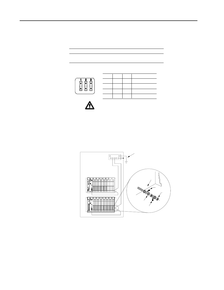
Configure Processor Chassis
Set the backplane switches located near the upper leftĆhand corner of the chassis backplane.
If you:
are not using expansion chassis
are using expansion chassis
number the chassis:
set the chassis number to 0
(processor module must be in chassis 0)
consecutively starting with 0
O
N
O
F
F
Switch:
1
2
3
Chassis Number
on
off
on
on
on
off
off
off
off
off
off
off
0
1
2
3
ATTENTION:
Number the chassis so that chassis o and the highest
numbered chassis have the same power supply. Failure to configure the
chassis in this way could result in unpredictable operation.
Ground Processor and I/O Chassis
Enclosure
Grounding electrode conductor
To grounding
electrode
system
Ground
bus
I/O chassis wall
Ground
lug
Nut
Star
washer
Ground lug