Installing a backup system chapter 2, Configuring the i/o chassis – Rockwell Automation 1775-MX_S4A,D17756.3.1 User Manual PLC-3 BACKUP CONC(OR.DU1 User Manual
Page 22
Installing a Backup System
Chapter 2
2-7
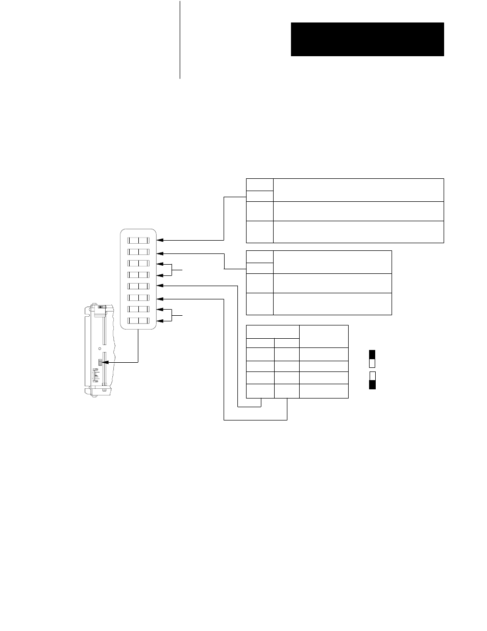
You must configure all I/O chassis for backup mode operation. Each I/O
chassis has eight switches. Two of the switches, switches 2 and 8, are
especially important because they affect the operation of a backup system.
See Figure 2.4 for the function and location of the I/O chassis switches.
Figure 2.4
Location and Function of I/O Chassis Backplane Switches
1
2
3
4
5
6
7
8
Outputs of this I/O chassis remain in their last state when
a fault is detected by this I/O adapter.
Outputs of this I/O chassis are turned off when a fault is
detected by this I/O adapter.
ON
Switch
1. CAUTION: If you set this switch to the ON position, when a fault is detected, outputs connected to this
chassis remain in their last state to allow machine motion to continue. We recommend that you set
switch 1 to the OFF position to de - energize outputs wired to this chassis when a fault is detected.
2. The 1771 - AS adapter does not support 1 - slot or 1/2 - slot addressing. When you use this
adapter, set switches 5 and 6 to the OFF position.
3. The 1771 - ASB series A adapter does not support 1/2 - slot addressing.
NOTES:
Pressed in
at top Closed (ON)
Pressed in at
bottom Open (OFF)
5
OFF
ON
OFF
ON
6
OFF
OFF
ON
ON
2 - slot
1 - slot
1/2 - slot
Not allowed
Switches
1
1
OFF
Last State
The I/O chassis can be restarted from
the processor.
The processor is locked out from
restarting the I/O chassis after a fault.
ON
Switch
2
OFF
Processor Restart Lockout
Always On
Always On
Addressing
2
2, 3
16191
OFF ON
Configuring the I/O Chassis