Diagnosing faults chapter 6 – Rockwell Automation 1775-MX_S4A,D17756.3.1 User Manual PLC-3 BACKUP CONC(OR.DU1 User Manual
Page 108
Diagnosing Faults
Chapter 6
6-4
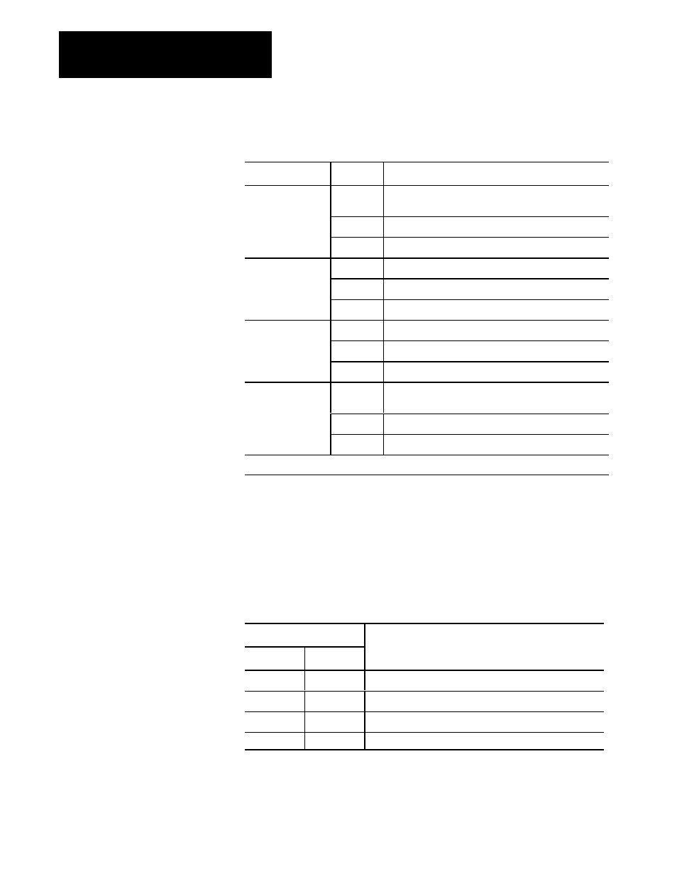
Table 6.B
Status Indicators for Backup Processor
Indicator
Status
Description
PROCESSOR
GREEN
Backup processor is active (normal operation in backup
mode)
RED
Major fault occurred
OFF
Power is off in the backup processor
OUTPUTS
GREEN
Not used
RED
Major fault*
OFF
Backup mode
PROGRAM
GREEN
Backup processor is in program load mode
RED
Major fault
1
OFF
Backup processor is not in program load mode
ACCESS
GREEN
A peripheral device is connected to a peripheral
communication channel and is onĆline (channel active).
RED
A peripheral device is editing the program or major fault
1
OFF
No peripheral communication channels are active.
1. When automatic switchover is selected, a major fault will turn all four status indicators red.
Diagnosing Faults with Module Status Indicators
All PLC-3 modules have two self-test indicators. Table 6.C describes how
to interpret these indicators.
Table 6.C
Module SelfĆTest Indicators
Indicator & Status
PASS
FAIL
Description
ON
OFF
Normal operation
OFF
ON
Module fault
ON
ON
PowerĆup or system reset
OFF
OFF
Processor shut off
Most PLC-3 modules have one or more indicators to help you pinpoint the
location of a fault. (See Figure 6.2 through Figure 6.4) Table 6.D through
Table 6.F describe how to interpret the indicators on each module.