Message packet formats chapter 5 – Rockwell Automation 1770-KF2 Data Highway or Highway Plus Interface Module User Manual User Manual
Page 93
Message Packet Formats
Chapter 5
5-14
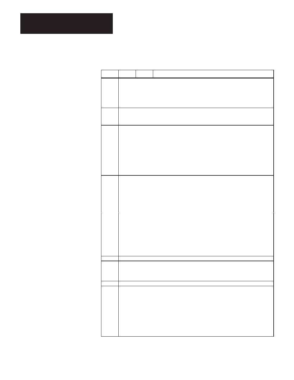
Table 5.C
Contents of Status DATA for 1773-KA Modules
Byte
Bit
Value
Meaning
1
Operating Status of Controllers on the Loop
0
1
2
3
4
5
6
7
1
1
1
1
1
1
1
1
If
Controller 1
Is Active
”
Controller 2
”
”
Controller 3
”
”
Controller 4
”
”
Controller 5
”
”
Controller 6
”
”
Controller 7
”
”
Controller 8
”
2
Station Interface Type
0-3
8
9
1773-KA, Data Highway Port
1773-KA, RS-232-C Port
4-7
8
PLC-4 Microtrol Processor
3-4
Data Highway Port Options
0
0
1
57,600 Bits per Second
Undefined
1
--
Not Used
2
0
1
Privileged Commands Enabled
Privileged Commands Disabled
3
0
1
Unprotected Commands Enabled
Unprotected Commands Disabled
4
0
1
Protected Commands Enabled
Protected Commands Disabled
5-7
--
Not Used
8-15
--
Octal Station Number
5-6
RS-232-C Port Options
0
0
1
Even Parity
No Parity
1-3
0
1
2
3
4
5
6
7
19,200
bps
8,600
bps
4,800
bps
2,400
bps
1,200
bps
600
bps
300
bps
110
bps
4-10
--
Not Used
11
0
1
Protected Commands Enabled
Protected Commands Disabled
12
0
1
Embedded Responses Enabled
Embedded Responses Disabled
13
0
1
Unprotected Commands Enabled
Unprotected Commands Disabled
14
0
1
Privileged Commands Enabled
Privileged Commands Disabled
15
0
1
Half-Duplex Protocol
Full-Duplex Protocol
7-8
Starting Byte Address of Diagnostic Timers and Counters
9
Module Series and Revision Level
0-4
0
1
Revision A
Revision B, Etc.
5-7
0
1
Series A
Series B, Etc.
10
--
--
Not Used
11-114
Eight 13-byte groups of processor status data, one group for each of eight possible controllers on the loop. If a particular controller on the loop is
not active or does not respond to the diagnostic status command, its 13 status bytes will be all zeros. Otherwise, each group of processor status
bytes will contain the following:
Byte 1
Program ID
2
Processor ID
3
Pointer to Start Program
4
Pointer to End of Available Memory
5
Size of I/O
6
Processor Error Code
7
Error Word Address (Low Byte)
8
Error Word Address (High Byte)
9
Processor Mode
10
Pointer to END Statement (Low Byte)
11
Pointer to END Statement (High Byte)
12
Pointer to End of Used Memory (Low Byte)
13
Pointer to End of Used Memory (High Byte)