Data encoding and addressing chapter 6 – Rockwell Automation 1770-KF2 Data Highway or Highway Plus Interface Module User Manual User Manual
Page 148
Data Encoding and Addressing
Chapter 6
6-11
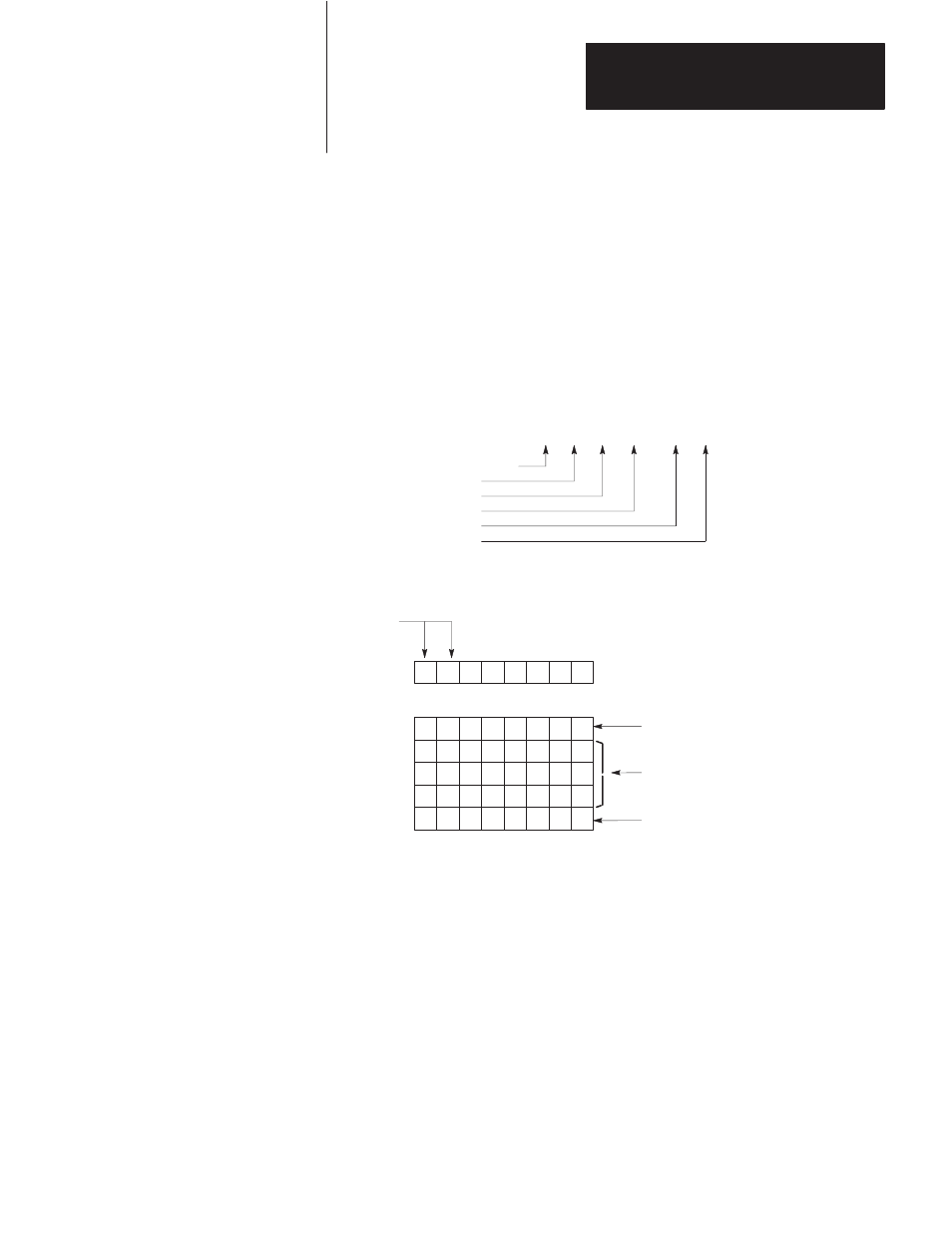
In Figure 6.7, the Level 5 address is 260 (decimal), which is too large to
fit in one byte. Therefore, a byte of all 1’s is used to delimit the 2-byte
address value for this level. The value 260 is then coded low byte first.
Note that the last level (Level 6 in this example) must be specified in the
address field even though it is equal to the default value of zero.
Figure 6.7
Example of PLC-3 Logical Binary Addressing Format
>
PLC-3 Extended Address
Level 1
Level 2
Level 3
Level 4
Level 5
Level 6
E3 .
8 . 260 . 0 . 0
X .
Logical Addressing Format
0
0
6
5
1
0
4
3
1
1
2
1
0
0
0
0
0
0
1
0
0
0
1
1
1
1
1
1
1
1
0
0
0
0
0
1
0
0
0
0
0
0
0
0
0
1
0
0
0
0
0
0
0
0
Always
Byte 1
Byte 2
Byte 3
Byte 4
Byte 5
Byte 6
Byte 1
Is the flag byte. In this case it indicates that the addresses for Levels 3, 4,
and 6 are specified in the bytes that follow. Default values are used for
Levels 1, 2, and 5.
Level 1
Level 2
Level 3
Level 4
Level 5
Level 6
(Default = 3 for Data Table)
Byte 2
Is the value of the Level 3 address.
Byte 5
Is the high byte of the Level 4 address. Note that Bytes 4 and 5 together give
a value of 260 for the Level 4 address.
Byte 3
Is a delimiter that says the next two bytes are one address.
Byte 4
Is the low byte of the Level 4 address .
(Default = Current Context)
(Value = 8)
(Value = 260)
(Default = 0)
(Value = 0)
Zero
Flag Bit for Level:
Byte
Byte 6
Is the value of the Level 6 address. Even though it is the default value, it must
be specified because it is the last level in the desired extended address.
= Data Table Area
=
=
=
=
=
Context
Section
File
Structture
Word
11261