Dimension drawings, All dimensions are in mm (inches) – Rockwell Automation 1404-M4_M5_M6_M8 Powermonitor 3000 Installation Instructions, PRIOR to Firmware rev. 3.0 User Manual
Page 56
Publication 1404-IN007D-EN-P - October 2004
56 Powermonitor 3000
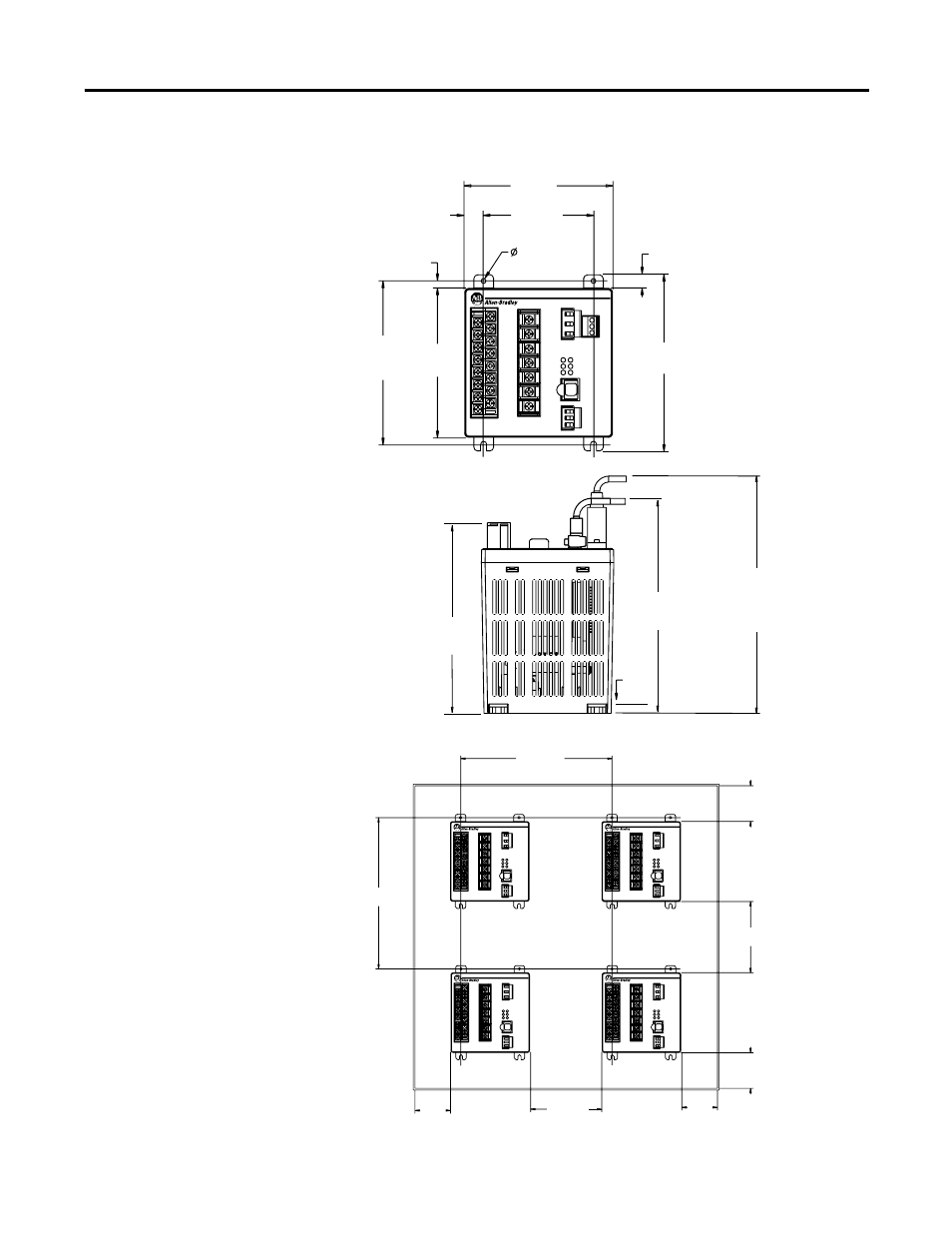
Dimension Drawings
Figure 41 Master Module Dimensions
Figure 42 Master Module Spacing
203.2 (8.000)
Used With -232
Communications
Options
Powermonitor 3000
14.66
(0.577)
114.30
(4.50)
85.0
(3.346)
Mounting
4.57 (0.180)
4 Places
10.43
(0.411)
5.35
(0.211)
125.0
(4.921)
Mounting
114.30
(4.50)
135.15
(5.321)
184.15 (7.250)
Used With
Display Module
163.17 (6.424)
Used Without
Display Module
5.60
(0.22)
All dimensions are in mm (inches).
Powermonitor 3000
Powermonitor 3000
Powermonitor 3000
Powermonitor 3000
50.8
(2.00)
50.8
(2.00)
50.8 (2.00)
Minimum
(See Note 3)
50.8 (2.00)
Minimum
(See Note 3)
101.6 (4.00)
(See Note 2)
101.6 (4.00)
(See Note 2)
215.9 (8.50)
(See Note 1)
215.9 (8.50)
(See Note 1)
General Notes:
1. Recommended spacing provides
reasonable wiring clearance and ventilation.
2. Maintain approximately 102 mm (4.00 in.) clearance
between master modules and other electrical
equipment.
3. Do not block cooling vents. Wiring and other
obstructions must be 50 mm (2.00 in.) minimum
from top and bottom of unit.
4. Mount with ventilation openings in top and bottom
to provide optimum free convection cooling.
5. Refer to Specifications for ambient temperature
requirements.