Led indicators – Rockwell Automation 1404-M4_M5_M6_M8 Powermonitor 3000 Installation Instructions, PRIOR to Firmware rev. 3.0 User Manual
Page 11
Publication 1404-IN007D-EN-P - October 2004
Powermonitor 3000 11
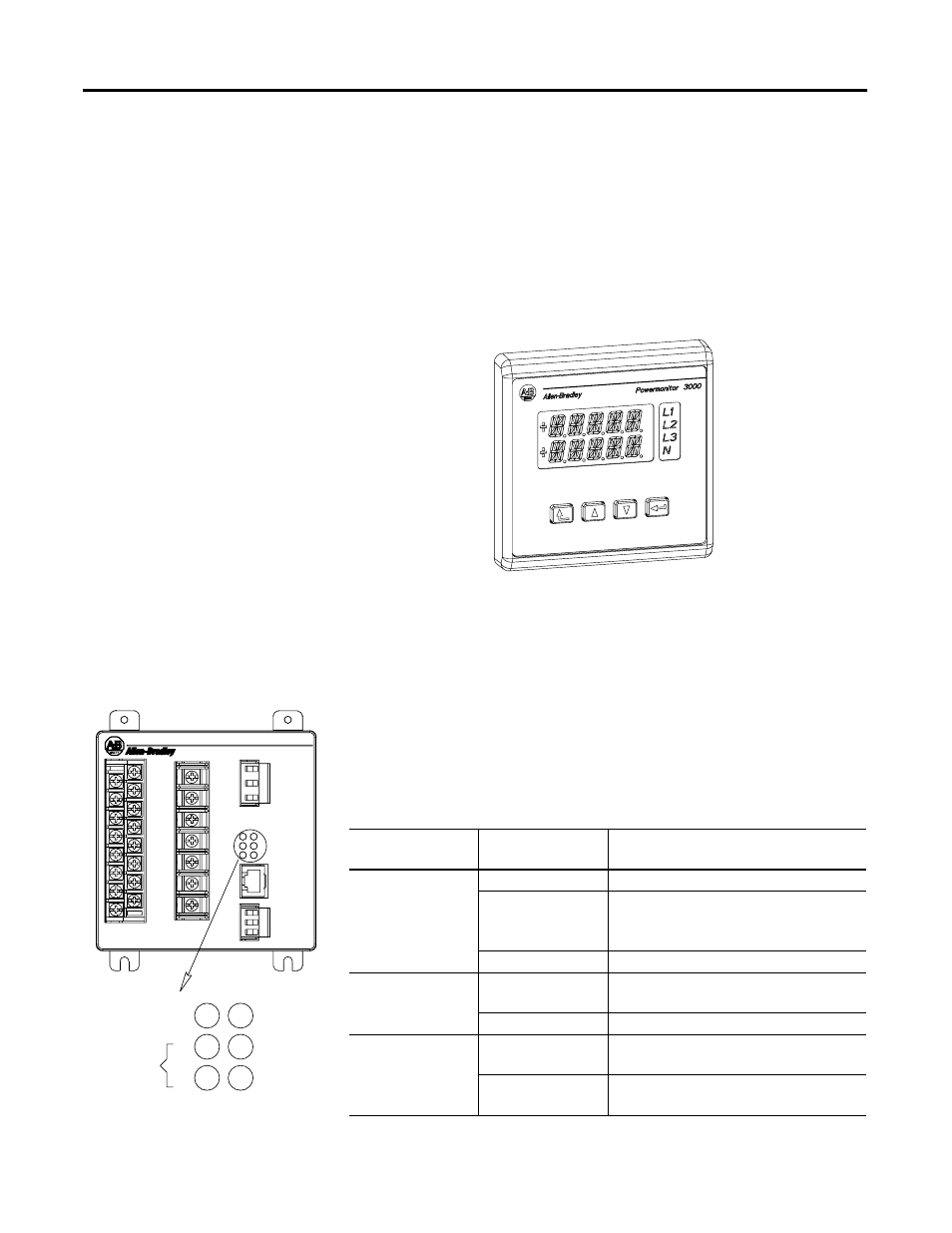
The Display Module is shipped with a 3-meter (10 ft) long, shielded
4-pair cable that provides power and serial communications between
the Master Module and the Display Module. The Display Module fits
into a standard ANSI four inch analog meter cutout for panel
mounting. Only one Display Module may be connected to a Master
Module, although you may use one Display Module to configure and
monitor any number of Master Modules; one at a time.
Figure 4 Display Module
LED Indicators
The Powermonitor 3000 is equipped with six bi-color light emitting
diodes (LED’s) arranged as shown in Figure 5.
Figure 5 LED Indicators
The three LED’s on the left display the same information on
Powermonitor 3000 modules with any communication option
including native RS-485 communications only. The three LED’s on the
right have different labels and different indications depending on the
communications option selected, as shown in the charts below.
Powermonitor 3000
RX
TX
RS-485
MODULE
STATUS
Table 6 LED Indicators All Powermonitor 3000 Models
LED
LED Color
LED State and Communications
Condition
Module Status
Off
Control power is off or insufficient
Steady Red
Major fault; internal self-test has failed. If a
power cycle does not correct the problem,
call customer support
Steady Green
Powermonitor 3000 is operating normally
RS-485 RX
Off
The RS-485 bus is idle; no active data is
present
Flashing Green
Active data is present on the RS-485 bus
RS-485 TX
Off
Powermonitor 3000 is not transmitting data
onto the RS-485 bus
Flashing Green
Powermonitor 3000 is transmitting data
onto the RS-485 bus