Control power, Status inputs, Figure 27 control power – Rockwell Automation 1404-M4_M5_M6_M8 Powermonitor 3000 Installation Instructions, PRIOR to Firmware rev. 3.0 User Manual
Page 36
Publication 1404-IN007D-EN-P - October 2004
36 Powermonitor 3000
Control Power
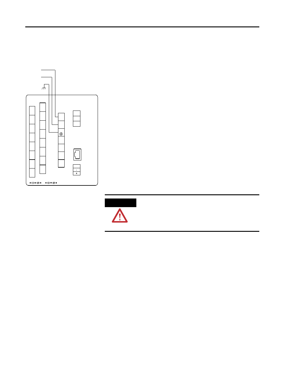
Figure 27 Control Power
The Powermonitor 3000 draws a nominal 15VA control power. Catalog
numbers 1404-MxxxA-xxx require nominal control power of 120 to
240V ac or 125 to 250V dc. The power supply is self-scaling. Catalog
number 1404-MxxxB-xxx require nominal control power of 24V dc.
Refer to Technical Specifications on page 59 for acceptable control
voltage ranges and wiring termination information.
We strongly recommend the use of a separate source of control power
from the power system being monitored. For applications where
power system information is critical, consider the use of a
user-supplied uninterruptible power supply so that the Powermonitor
3000 continues to operate during power system events such as
significant sags, swells, and transient disturbances.
It is required to connect your Powermonitor 3000 control power
through user-supplied disconnecting means and overcurrent
protection.
Status Inputs
All Status Inputs are common to an internal 24VDC source on the
SCOM terminal. Status input terminals S1 and S2 are positive polarity
and SCOM is negative polarity.
For optimal EMC performance, we recommend wiring the status
inputs using shielded cable, Belden™ 8771 or equivalent, with the
cable shield grounded at both ends where possible. See Figure 28.
L1
N/L2
Local
Frame
Ground
Powermonitor 3000
MASTER MODULE
R14
R11
R12
N/C
N/C
I1-
I1+
I2-
I2+
I3-
I3+
I4-
I4+
Y
K
Z
R14 R11 R12 Y
K
Z
L1
(+)
L2
(-)
GRD
V1
S1
S2
SCOM
V2
V3
N
DISPLAY
MODULE
SHLD
RS-485
ATTENTION
Do not apply an external voltage to a Status Input.
These inputs have an internal source and are
intended for dry contact input only. Applying a
voltage may damage the associated input or internal
power supply.