Rockwell Automation 1404-M4_M5_M6_M8 Powermonitor 3000 Installation Instructions, PRIOR to Firmware rev. 3.0 User Manual
Page 14
Publication 1404-IN007D-EN-P - October 2004
14 Powermonitor 3000
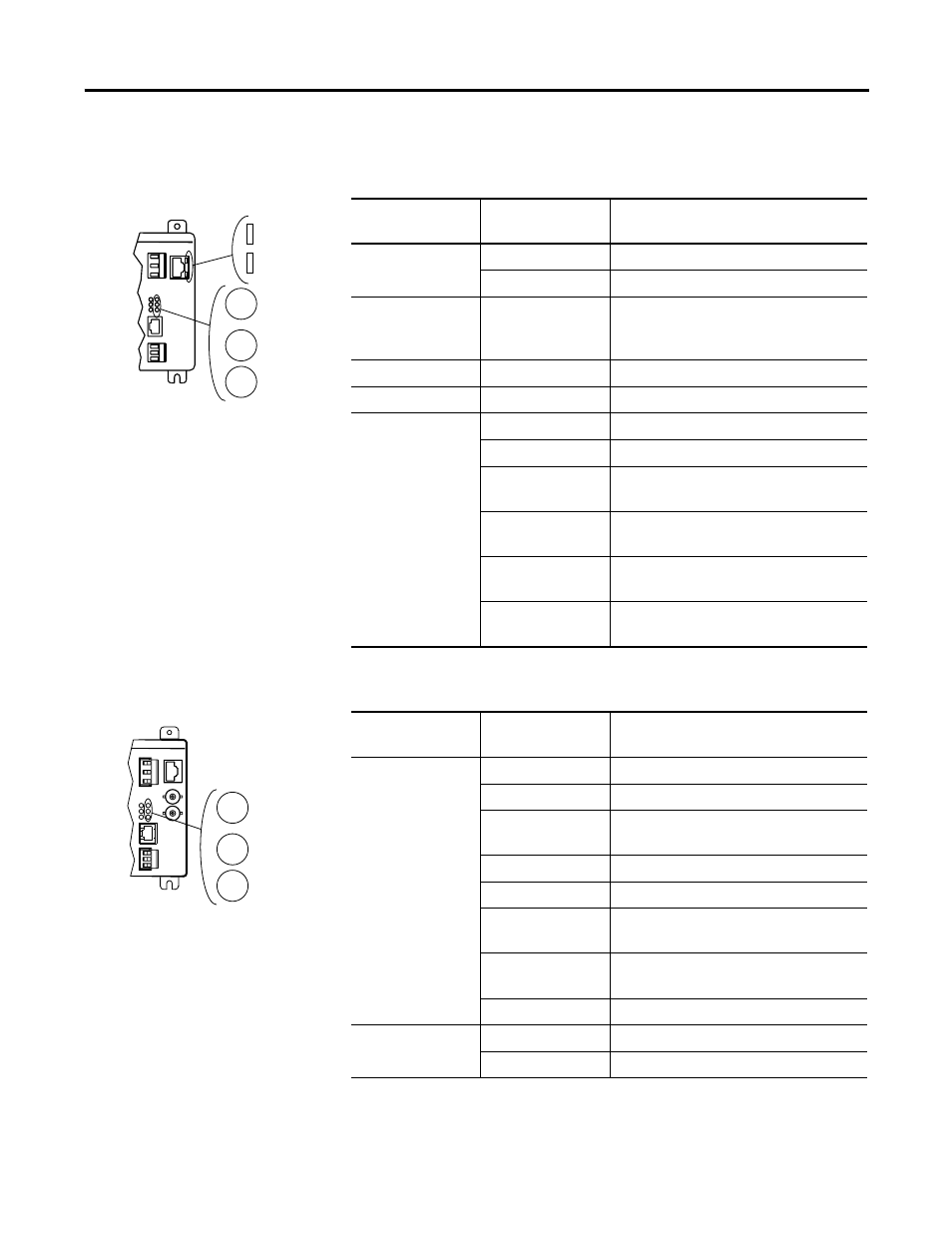
Table 12 Ethernet/IP Optional Communications (Series B catalog numbers ending
in -ENT)
LED
LED Color
LED State and Communications
Condition
LNK
Off
No valid physical Ethernet connection
Steady Green
Valid physical Ethernet connection
ACT
Strobing or
Solid Yellow
Powermonitor 3000 transmitting onto
Ethernet
F1
Off
Not Used
F2
Off
Not Used
NETWORK STATUS
Off
No power
Flashing Green
No established connections
Steady Green
Connected; has at least one established
connection
Flashing Red
Connection timeout; one or more
connections to this device has timed-out
Steady Red
Duplicate IP; the IP address assigned to this
device is already in use
Flashing Green/Red
Selftest; this device is performing a
power-up self test
Table 13 ControlNet Optional Communications (catalog numbers ending in -CNT)
LED
LED Color
LED State and Communications
Condition
CHAN A and
CHAN B
Off
No power or Channel disabled
Steady Red
Faulted unit
Alternating
red/green
Self-test
Alternating red/off
Incorrect node configuration
Steady green
Normal operation
Flashing green/off
Temporary errors or node is not configured
to go on-line
Flashing red/off
Media fault or no other nodes present on
network
Flashing red/green
Incorrect network configuration
Status
Off
Normal operation
Flashing green
Communication card power-up self-test
F1
LNK
ACT
F2
NETWORK
STATUS
Powermonitor 3000
CHAN A
CHAN B
NETWORK
STATUS
Powermonitor 3000