Installation overview – Rockwell Automation 1329I Integrated AC Drive/Motor, Series B FRN 3.X User Manual
Page 8
Checklist-2
Installation Checklist
1329I-5.5 Integrated Drive/Motor — January, 2000
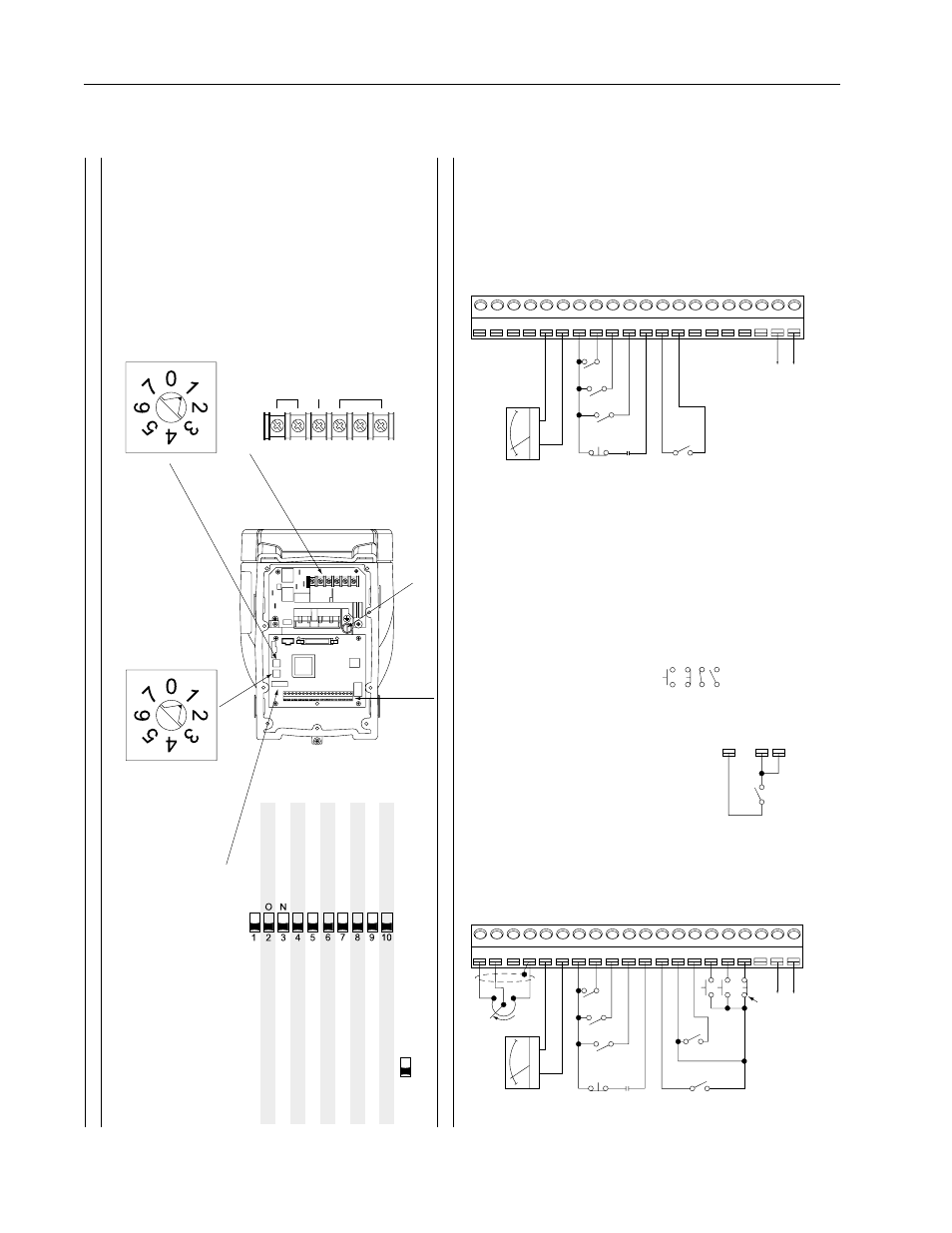
Installation Overview
PE
DC Bus (Do Not
Wire)
DBR (Do Not
Wire)
A
C
Inputs
A
C
Input P
o
wer Connections
1
2
3
4
5
6
7
8
9
10 11 12 13 14 15 16 17 18 19 20
10
V
olt Ref
erence
➊
0 – 10V DC Speed Ref
erence Input
4 – 20 mA Speed Ref
erence Input
Common
0 – 10
V
olt Output
Common
Speed Preset 2
Speed Preset 1
Speed Preset 0
F
orw
ard/Re
verse
24 V
olt
DC
➌
RPM/P
ercent Load Displa
y
Reset
Star
t
Stop
➌
24
V
olt DC Common
N.O
. Rela
y
Rela
y Common
24 V
olt
DC
➋
Function Loss
➋
-+
RPM
% Load
OFF
ON
Enab
led
Te
rminal Bloc
k
F
aulted
Enab
led
Constant
Ramp-to-Rest
Disab
led
F
rom T
e
rminal
Bloc
k
F
rom T
e
rminal
Bloc
k
F
rom EEPR
OM Memor
y
Run On P
o
w
er Up
Speed Ref
erence
➊
Rela
y Control Output
A
uto Restar
t
Torque Cur
ve
Stop
Re
verse
Minim
um Speed
Star
t Mode
➊
P
a
rameter Mode
➋
Disab
led
Oper
ator Controls
Running
Disab
led
V
a
riab
le
Coast-to-Rest
Enab
led
0 Hz
F
rom Oper
ator Controls
F
rom Setup Switches
Setup DIP Switc
h (SW3)
➊
Switches 2 and 9 apply to local oper
ator control units only
.
➋
Switch 10 applies to the De
viceNet Comm
unication option only
.
1
2
3
4
5
6
7
8
9
10 11 12 13 14 15 16 17 18 19 20
10
V
olt Ref
erence
➊
0 – 10V DC Speed Ref
erence Input
4 – 20 mA Speed Ref
erence Input
Common
0 – 10
V
olt Output
Common
Speed Preset 2
Speed Preset 1
Speed Preset 0
F
orw
ard/Re
verse
24 V
olt
DC
➌
RPM/P
ercent Load Displa
y
Reset
Star
t
Stop
➌
24
V
olt DC Common
N.O
. Rela
y
Rela
y Common
24 V
olt
DC
➋
Function Loss
➋
-+
+10V DC
5K
Ω
RPM
Fwd
Re
v
% Load
13
16 17
Maintained 2-Wire Star
t.
Momentar
y 3-Wire Star
t.
0 = 1 Second Accel/5 Sec Decel
1 = 5 Seconds (Def
ault)
2 = 10 Seconds
3 = 15 Seconds
4 = 20 Seconds
5 = 30 Seconds
6 = 60 Seconds
7 = 90 Seconds
0 = 1500 RPM (50 Hz)
1 = 1800 RPM (60 Hz) Def
ault
2 = 2100 RPM (70 Hz)
3 = 2400 RPM (80 Hz)
4 = 2700 RPM (90 Hz)
5 = 3000 RPM (100 Hz)
6 = 3300 RPM (110 Hz)
7 = 3600 RPM (120 Hz)
Max Speed Switc
h (SW2)
Accel/Decel Switc
h (SW1)
Contr
ol Signal
T
erminal Bloc
k
Selector
s and Connector
s
Standar
d Unit
Local Operator Contr
ol Unit
Connect to e
xter
nal de
vice
.
➋
The jumper betw
een ter
minals 7 and 11 m
ust be remo
ved when
wir
ing the Function Loss input.
See Section 7.1 f
or more inf
or
mation.
➌
The jumper betw
een ter
minals 13 and 17 m
ust be remo
ved when
wir
ing the Stop input.
See Section 7.6 f
or more inf
or
mation.
➊
An e
xter
nal 0 to 10 v
olt or 4 to 20 mA speed ref
erence source can
be connected.
See Section 7.5.3 of the User Man
ual f
or more inf
or
mation.
= N.O
. Momentar
y Contact
= N.C
. Momentar
y Contact
= Maintained Contact - Closed
= Maintained Contact - Open
Ground / Protectiv
e Ear
th
= Def
ault Setting (OFF P
osition)
Connect to e
xter
nal de
vice
.
DC+
DC-
DBR
T/L3
S/L2
R/L1