6 wiring start / stop control, Wiring start / stop control -9 – Rockwell Automation 1329I Integrated AC Drive/Motor, Series B FRN 3.X User Manual
Page 37
Step 7 - Wire the Control Signal Terminal Block
7-9
1329I-5.5 Integrated Drive/Motor — January, 2000
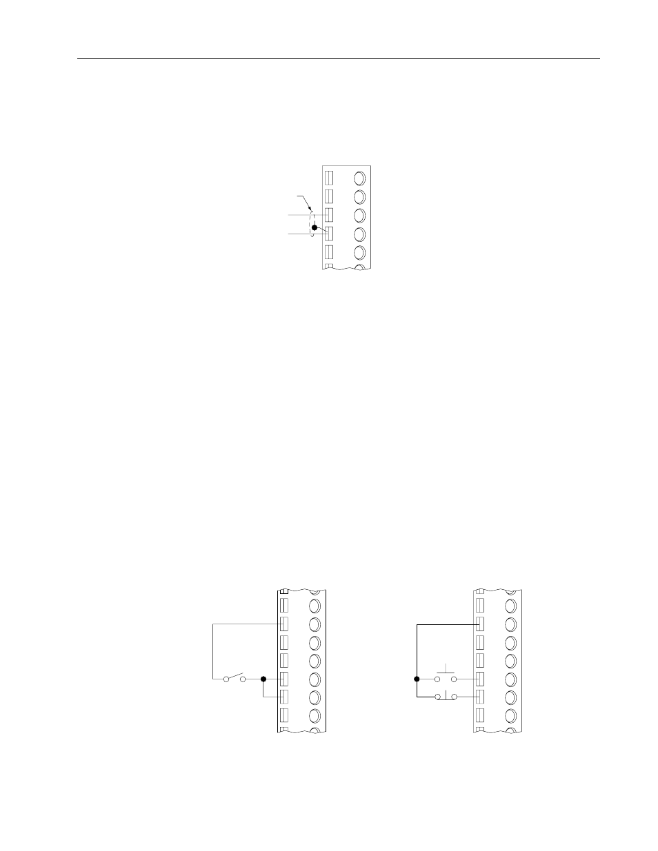
4 to 20 mA External Speed Reference
To use an external 4 to 20 mA signal to set the speed reference, connect the signal leads
as shown in Figure 7.11. 4 to 20 mA = minimum speed to maximum speed.
Figure 7.11
4 to 20 mA External Speed Reference Wiring
7.6
Wiring Start / Stop Control
Important:
The terminal block start function is only active when in terminal block
start mode.
The system looks for an open-to-closed transition at the Start input before starting the
unit unless you have the Run on Power Up switch (setup DIP switch 1, see Section
8.3.1) set to ON. If you use a maintained start device and power to the unit is lost, you
must open and reclose the start device before the unit will start again. Both the Stop and
the Function Loss input signals must be present and there must be no active faults for
the unit to start.
In order for the unit to run, you must maintain a signal at the Stop input. If the signal
is interrupted, the unit coasts to rest (default) or ramps to rest (user option). To restart
the unit, you must restore the signal and reassert the Start input.
Figure 7.12 illustrates wiring for a maintained 2-wire and for a momentary 3-wire
Start / Stop control
Figure 7.12
Start / Stop Control Wiring
➊
The jumper between terminals 13 and 17 must be removed when wiring the Stop input.
➋
Refer to Chapter 8 to select a stop method via SW3 Selector Switch.
12
345
4 – 20 mA Speed Reference Input
Common
Shield
(Drive end only)
12
13
14
15
16
17
18
24 Volt DC
➊
Start
Stop
➊
➋
12
13
14
15
16
17
18
24 Volt DC
➊
Start
Stop
➊
➋
Maintained 2-Wire
Momentary 3-Wire