Installation overview, Control sign al terminal block conn ection s, Selectors an d con nectors – Rockwell Automation 1329I Integrated AC Drive/Motor, Series A User Manual
Page 6: Lo ca l op erato r co ntrol un it sta nda rd un it
Checklist-2
Installation Checklist
1329I-5.0 Integrated Drive/Motor — January, 1999
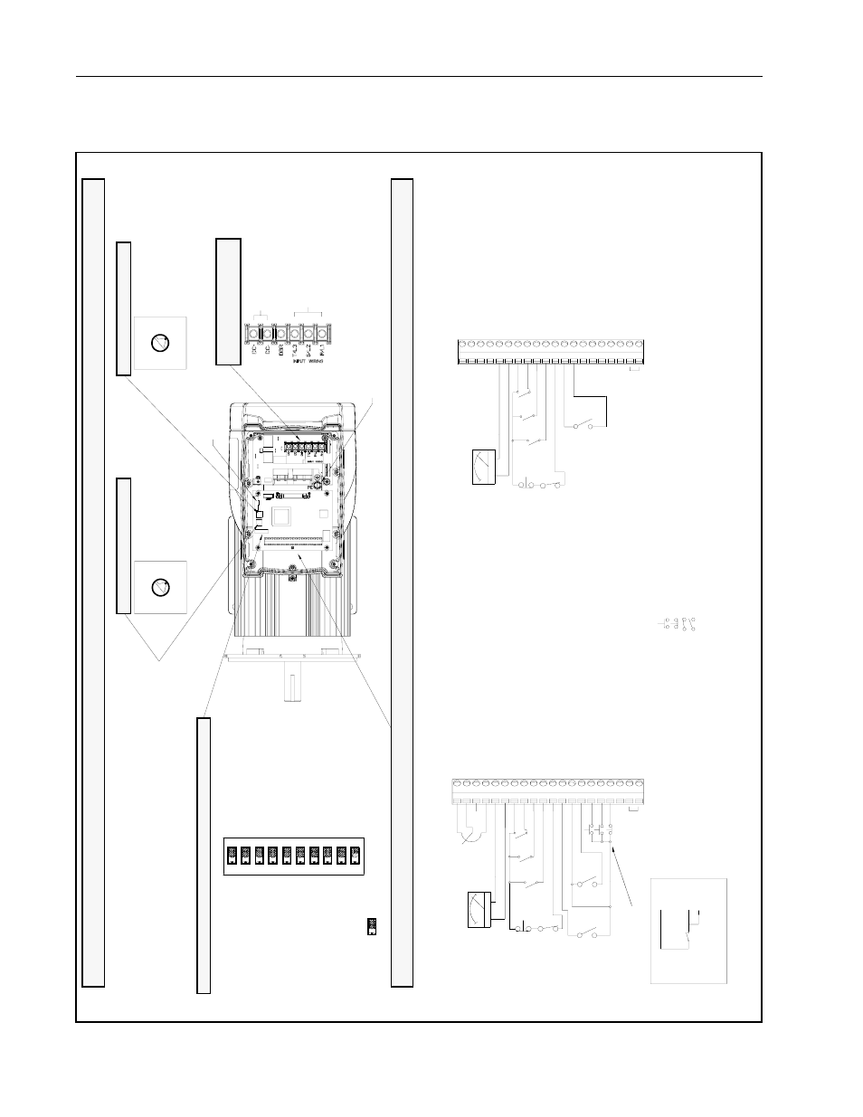
Installation Overview
Accel
/ De
cel
Swit
ch
Max
Sp
ee
d
Swit
ch
S
e
tu
p
DIP S
witch
T
op V
iew o
f Un
it
With
Cove
r Re
move
d
Di
spl
a
y Boar
d
- DBR (Do
Not W
ire
)
Co
nn
ec
tio
n
s
AC I
npu
t Po
we
r
DC Bu
s (Do
Not
Wi
re)
A
C
Inp
u
ts
➋
1
2
RP
M /
%Lo
ad Disp
lay
1
0
Sp
ee
d Pr
es
et 0
11 Fu
nct
ion
L
o
ss
13
2
4
V
D
C
14
F
o
rw
a
rd/
Re
ve
rse
15 Reset
16
S
ta
rt
1
8
24
DC Co
mmo
n
1
9
N.O
. Rela
y
20 Re
lay Com
m
on
=
N.O. Mom
entar
y
Co
ntact
=
M
a
in
tained
Con
tact -
Open
=
M
a
in
tained
Con
tact -
Clos
ed
=
N.C
. Mo
men
tary C
onta
c
t
Main
ta
in
ed 2-
Wir
e
➊
Star
t
17
16
%L
O
A
D
RP
M
13
RE
V
+ -
FWD
➋
5K
9 Sp
eed P
reset
1
5
0
to
1
0
V
Ou
tp
ut
7
24V
DC
8
S
p
ee
d Pr
ese
t 2
2
0 to
1
0
V
Sp
d Ref
In
pu
t
3
4
t
o
20
m
A
Sp
d
R
e
f
In
p
u
t
+
10V
DC
1 1
0
Vo
lt
Re
fere
nce
G
round
M
o
m
e
nt
ar
y 3
-Wi
re
St
a
rt
Min S
pd fr
om T
e
rm
inal B
lock
Input
s
= D
e
fa
u
lt
Se
tt
in
g
(O
F
F
Po
s
itio
n
)
3 H
z
M
inimu
m S
peed
Re
verse
Enab
led
C
oast
-to-R
est S
top
8
6
7
An
alog
Spd R
e
f fr
om T
e
rmi
nal B
lock
➊
Spd R
e
f fr
om O
pera
tor C
ontro
ls
Relay
O
u
tput C
ontro
l: Run
n
ing
R
un O
n
Po
wer U
p
D
isabl
ed
Va
riable
Tor
que C
u
rve
Auto
Res
tart D
isabl
ed
4
5
3
2
N
1
O
9 10
(N
ot U
sed)
(N
ot U
sed)
➊
RP
M
%L
OA
D
+ -
Lo
ca
l
Op
erato
r Co
ntrol
Un
it
Sta
nda
rd Un
it
(0
to
M
a
x
Spd
)
0
= 1 s
e
c
ac
ce
l /
5 se
c d
e
c
e
l
1 =
5
se
c (
D
efa
u
lt
)
2 =
1
0
s
e
c
3 =
1
5
s
e
c
4 =
2
0
s
e
c
5 =
3
0
s
e
c
6 =
6
0
s
e
c
7 = 90
sec
6
2
3
45
1
0
7
Conne
ct
or
➊
S
lide
swit
ch
2
is
use
d
on
ly
wit
h
loc
a
l op
erat
or
co
nt
ro
l un
it
s.
C
onnec
t t
o
e
x
te
rnal
de
v
ice
su
c
h
a
s
PL
C
in
put
.
input
.
C
onnec
t t
o
e
x
te
rnal
dev
ice su
ch as P
L
C
3
45
1
2
7
0
6
0
=
15
00 RPM (50 Hz)
7
=
36
00
RPM
(120
Hz
)
6
=
33
00
RPM
(110
Hz
)
5
=
30
00
RPM
(100
Hz
)
4
=
27
00 RPM (90 Hz)
3
=
24
00 RPM (80 Hz)
2
=
21
00 RPM (70 Hz)
1
=
18
00 RPM (60 Hz)
(D
e
fau
lt)
Ru
n
O
n
P
o
we
r Up
E
n
ab
le
d
R
e
lay
O
u
tp
ut Co
ntrol
: Fau
lted
Au
to Re
start
Enab
led
Cons
tant
Torqu
e
Cu
rve
Ram
p
-to-
Rest
Stop
R
eve
rse D
isabl
ed (R
ever
se Lo
ckou
t)
6 C
o
m
m
o
n
➊
Control
Sign
al
Terminal Block
Conn
ection
s
Commo
n
4
1
2
RPM
/
%
Loa
d Disp
lay
10
S
p
e
ed P
rese
t 0
11
F
u
nct
io
n
Lo
ss
13
24V
DC
1
4
F
o
rw
ar
d/
R
e
ve
rs
e
15 Reset
16
St
art
18
24 DC Co
mmon
1
9
N.
O.
R
e
lay
2
0
Rel
a
y Comm
on
9 Sp
eed
Prese
t 1
5 0 to 10
V Ou
tpu
t
7 24
V DC
8 Sp
ee
d Pr
es
et 2
2 0 to 10
V Sp
d Re
f Inp
u
t
3
4
to
20
m
A
Sp
d
Re
f
In
pu
t
1 10
Vol
t Re
fe
re
nce
6
Co
mmo
n
Co
mmo
n
4
St
op
17
St
op
17
➊
Selectors
an
d Con
nectors
The j
u
mp
er bet
ween
term
inals
7 an
d 11
mus
t be r
e
mov
ed w
hen w
iring
the
Func
tion L
oss i
nput.
See S
ectio
n 7.1
for more i
n
formation
.
An ex
terna
l 0 to
10 v
o
lt or
4 to 2
0
m
A
spee
d refe
rence
sou
rce c
an be
conn
ected
.
See S
ectio
n 7.5
.3 for
m
o
re
info
m
a
tio
n.
T
he jum
per
betw
een te
rmin
als 7
and 1
1
m
ust b
e
rem
oved
whe
n
wir
ing th
e
F
unctio
n Los
s inp
u
t. Se
e Se
ction
7.1
fo
r m
o
re inf
o
rm
a
tion.