Chapter 4 – setup and commissioning, Intellivac configuration, Setup and commissioning – Rockwell Automation 1503VC IntelliVAC Contactor Control Module User Manual
Page 31: Chapter
Chapter
4
1503-UM051D-EN-P – June 2013
Setup and Commissioning
IntelliVAC Configuration
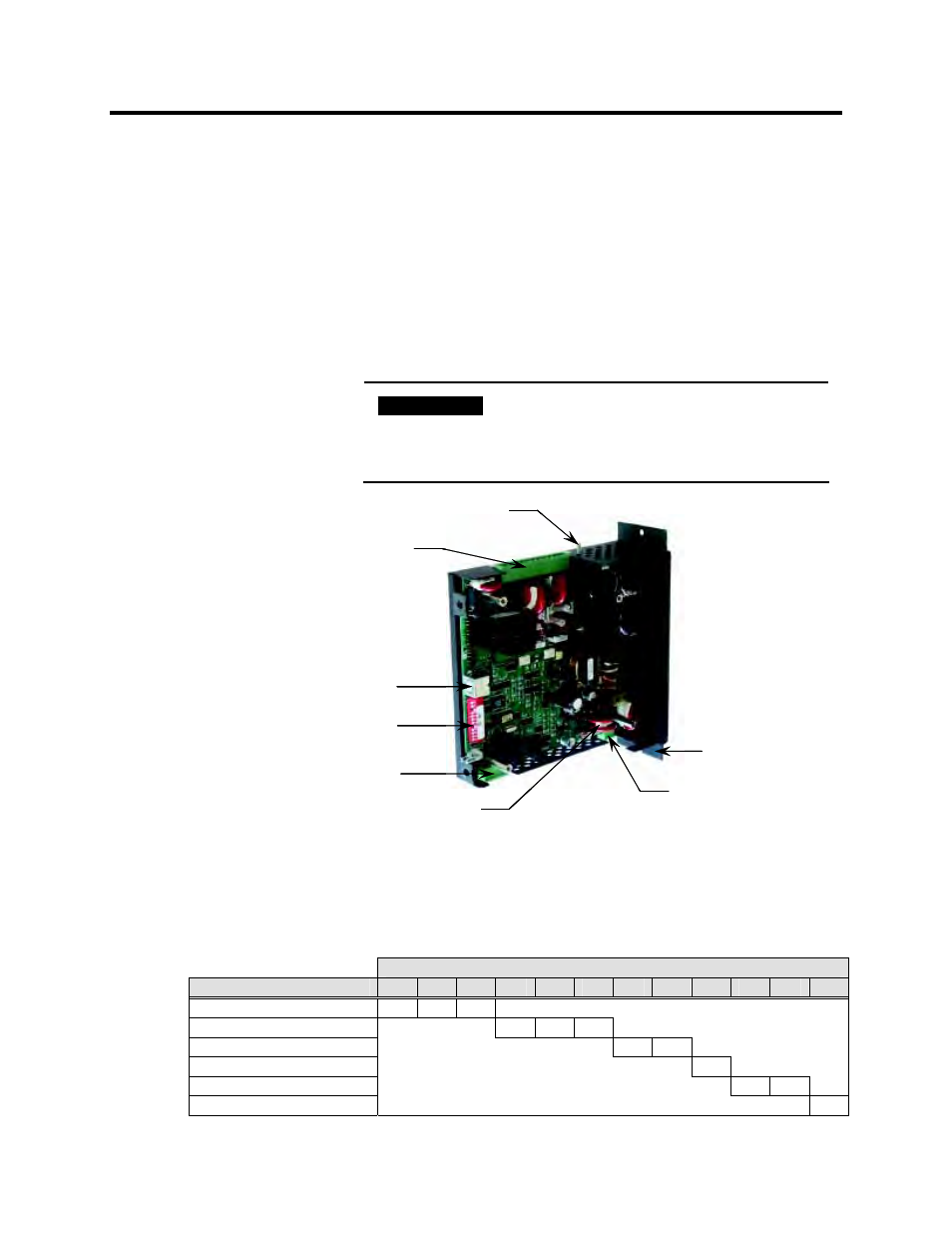
The IntelliVAC module is configured for a specific application by
setting DIP switches. They are accessed by loosening the two
screws on the front of the unit, and removing the cover by sliding it
forward. The switches are found on the front edge of the IntelliVAC
circuit board (see Figure 4-1). There are 12 switches, with number 1
being at the top next to the mini DIN connector. (Refer to Table 4.B).
I M P O R T A N T
I M P O R T A N T
Remove power from the module before
removing the cover and before changing the
DIP switch settings. The new settings are
recognized only on power-up.
Status Relay Outputs
Interface Connections
Ground Stud (Series A)
EEPROM Programming Port
(Mini DIN Connector)
DIP Switches
Ground Stud (Series B)
Supply Power Input
Internal Control Fuse
Status Relay Outputs
Interface Connections
Ground Stud (Series A)
EEPROM Programming Port
(Mini DIN Connector)
DIP Switches
Ground Stud (Series B)
Supply Power Input
Internal Control Fuse
Figure 4.1 – DIP Switch and Connector Locations
An IntelliVAC unit shipped separately from the factory will have a
default configuration per Table 4.A.
Table 4.A – DIP Factory Default Settings
DIP switch
Description
1
2
3
4
5
6
7
8
9
10
11
12
Altitude: 0 – 1000m
0
0
1
Drop-out time: 130 msec
0
1
1
Contactor config.: 400A EH
0
1
TDUV config.: No TDUV
0
Ext. cap TDUV time: 0.2 sec
0
0
*Power-Up Safety: Enable
0