Rockwell Automation 1503VC IntelliVAC Contactor Control Module User Manual
Page 15
Installation and Wiring
3-3
1503-UM051D-EN-P – June 2013
OEM
The IntelliVAC may be ordered as an OEM component. This allows
the OEM to mount the components in a configuration most suitable
to the motor controller equipment layout. Care must be exercised to
ensure the IntelliVAC has adequate ventilation provided around it.
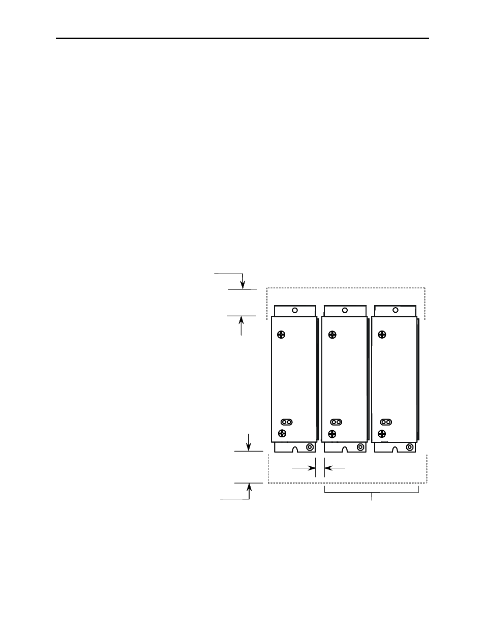
Refer to Figure 3.2 for mounting the IntelliVAC. It is recommended
that a minimum of 1.5 inches (38.1mm) of free air space be provided
between the IntelliVAC and any solid barrier above or below.
The OEM is responsible for controller fusing, motor overload
protection, control devices (eg.
Start/Stop push buttons), and wiring
between the IntelliVAC and 1502 vacuum contactor (using optional
wire harness). Wiring and mounting for optional items, such as
TDUV Capacitor are also the OEM’s responsibility. Refer to Figure
3.3 or 3.4 for basic connections.
An optional EMI filter is required to meet CE EMC requirements
(refer to Chapter 6 for recommended type).
38.1
(1.50)
38.1
(1.50)
6.4 (0.25)
Additional Modules
(as required)
Minimum bottom clearance
Minimum top clearance
Dimensions in mm (inches)
38.1
(1.50)
38.1
(1.50)
6.4 (0.25)
Additional Modules
(as required)
Minimum bottom clearance
Minimum top clearance
Dimensions in mm (inches)
Figure 3.2 – Typical Mounting Configurations
Note:
Adjacent IntelliVAC modules may be mounted with a
minimum separation of 6.4 mm (0.25 inches).