Rockwell Automation 1502 Medium Voltage 400A Contactor - Series E User Manual
Page 51
Rockwell Automation Publication 1502-UM052H-EN-P - June 2013
51
Maintenance
Chapter 4
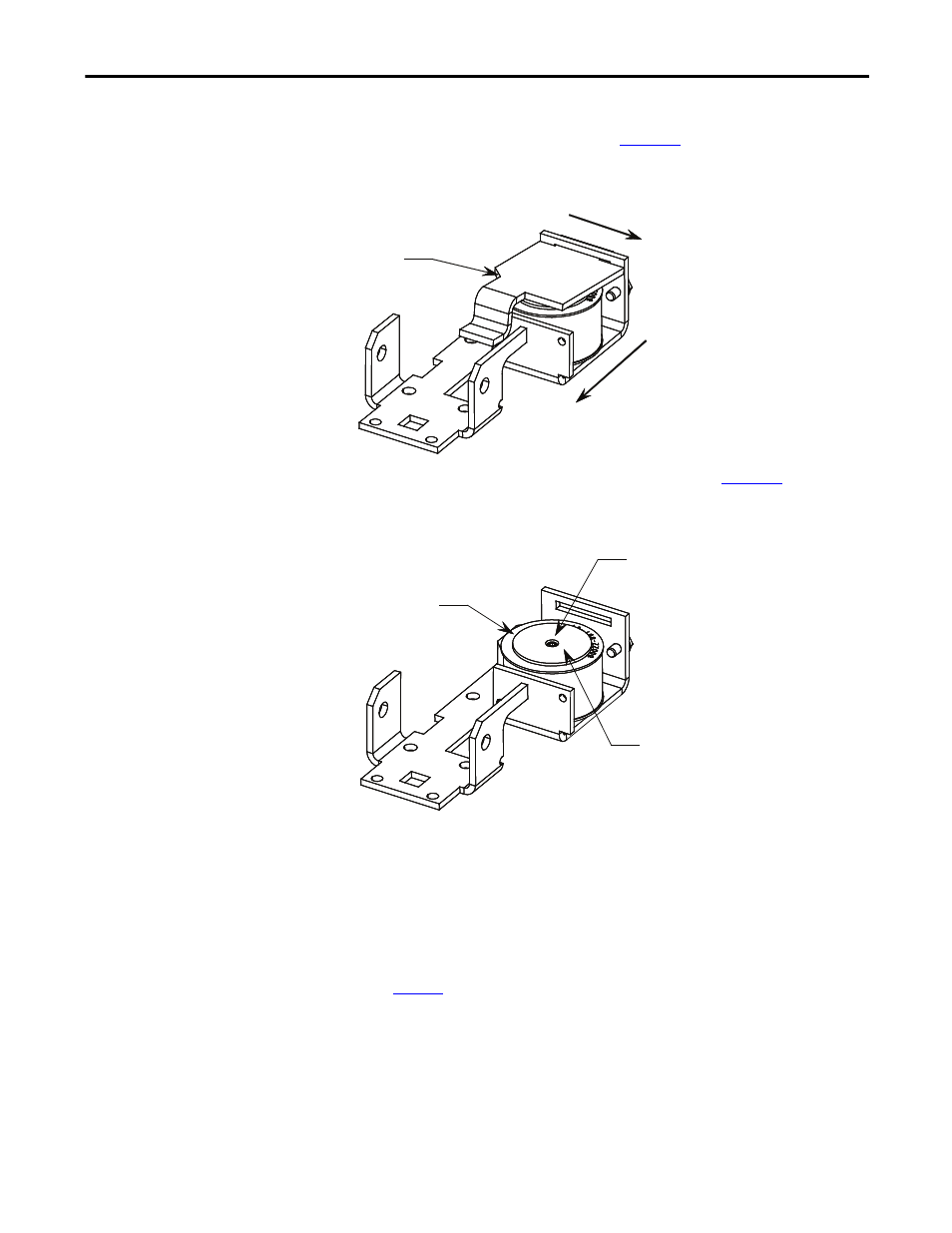
8. Remove the flapper by sliding it to the right until it stops and then pulling
it towards the front of the contact (
). The trip (magnet) coil and
coil core are now exposed (
Note: Contactor not shown for clarity).
Figure 47 - Removal of Flapper
9. Using a right angle Allen key, remove the coil core (
) and trip
(magnet) coil (
Note: Contactor not shown for clarity).
Figure 48 - Trip Coil and Core Removal
10. Slide the coil core from the trip (magnet) coil and then place the
replacement coil onto the coil core.
11. Connect the new trip (magnet) coil leads to the auxiliary contact assembly.
12. Re-assemble the mechanical latch and auxiliary assembly in reverse order
of this procedure.
13. Perform the auxiliary contact assembly adjustment procedure (see
Note: The contactor will not function correctly if this step is not
performed.
14. Verify that the replacement trip coil functions by using Test Power to close
(latch) the contactor. Complete the cycle by opening (tripping) the
contactor. Perform this sequence 2-3 times to ensure that the contactor
closes (latches and opens (trips) properly.
Flapper
Step 1:
Slide flapper to right.
Step 2:
Pull flapper forward to remove.
Magnet Coil
Coil Core
Use right angle Allen key
to remove coil core