Rockwell Automation 1502 Medium Voltage 400A Contactor - Series E User Manual
Page 43
Rockwell Automation Publication 1502-UM052H-EN-P - June 2013
43
Maintenance
Chapter 4
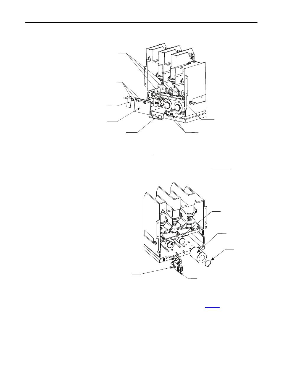
Figure 33 - Access to Coils
2. Remove the retaining ring from the core of the coil you wish to replace as
3. Loosen the auxiliary assembly retaining bolt and slide the assembly and the
coils forward and out of the contactor as shown in
.
Figure 34 - Coil Removal
4. Disconnect the coil leads (take note of their location). Connect the leads
of the new coil making sure that all metal-oxide varistors (MOVs) and/or
diodes are secure. Refer to the appropriate wiring diagram in this manual if
further control wiring details are required (see
5. Slide the new coil into position and install the retaining ring on the core.
Install the auxiliary assembly leaving the retaining bolt loose for adjustment
later. See the Auxiliary Contact Set-up Procedure (page 4-10) for
determining the position of the auxiliary assembly.
Auxiliary Actuator
Stop Bracket Bolts
Armature Stop Bracket
Armature Plate
Return Spring Actuator Plate
Grade 5 (5/16 Hardware) to mount
return spring actuator plate. Refer
to page 4-1 for torque values.
Grade 5 (5/16 Hardware) to mount
armature plate. Refer to page 4-1
for torque values.
Auxiliary Assembly
Retaining Bolt
Operating Coil
Operating Coil
Retaining Ring
Auxiliary Assembly