Auxiliary contact set-up procedure – Rockwell Automation 1502 Medium Voltage 400A Contactor - Series E User Manual
Page 44
44
Rockwell Automation Publication 1502-UM052H-EN-P - June 2013
Chapter 4
Maintenance
6. Install the armature plate, auxiliary actuator and stop bracket. Position the
stop bracket by resting it lightly against the armature plate.
Auxiliary Contact Set-up
Procedure
Refer to Chapter 6 for part number(s) required for this procedure.
To facilitate the set-up procedure, the contactor is held closed mechanically by
means of a clamping fixture as shown in Figure 4.13. It is important that the
contactor is held closed tightly with the armature plate against the magnet cores
when gauging the overtravel and auxiliary positioning.
To aid in closing the contactor mechanically, a clamping fixture is required. Allen-
Bradley part number
80154-149-51 is recommended.
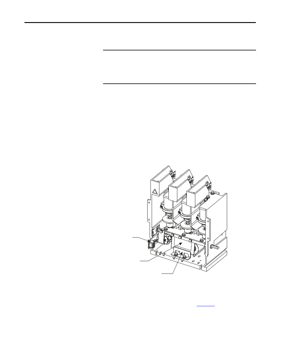
Figure 35 - Contactor Components
1. Loosen the nuts on auxiliary assembly retaining bolt. This requires
loosening and removal of the first nut which secures a ground wire at this
location. Leave on nut loosened just enough to permit the assembly to
slide along the adjustment slot as shown in
.
IMPORTANT
This procedure applies to adjustment of existing auxiliaries and installation of
new auxiliaries. Under normal conditions, auxiliaries will last at least
1,000,000 operations. If auxiliary contacts must be replaced, discard the entire
assembly and install a new assembly. This is easier than replacing a single
contact block.
Auxiliary Actuator
Armature Plate
Armature Stop Bracket