Rockwell Automation 20-750-PBUS Profibus DPV1 Option Module User Manual
Page 62
62
Rockwell Automation Publication 750COM-UM004B-EN-P - September 2012
Chapter 6 Acyclic Messaging
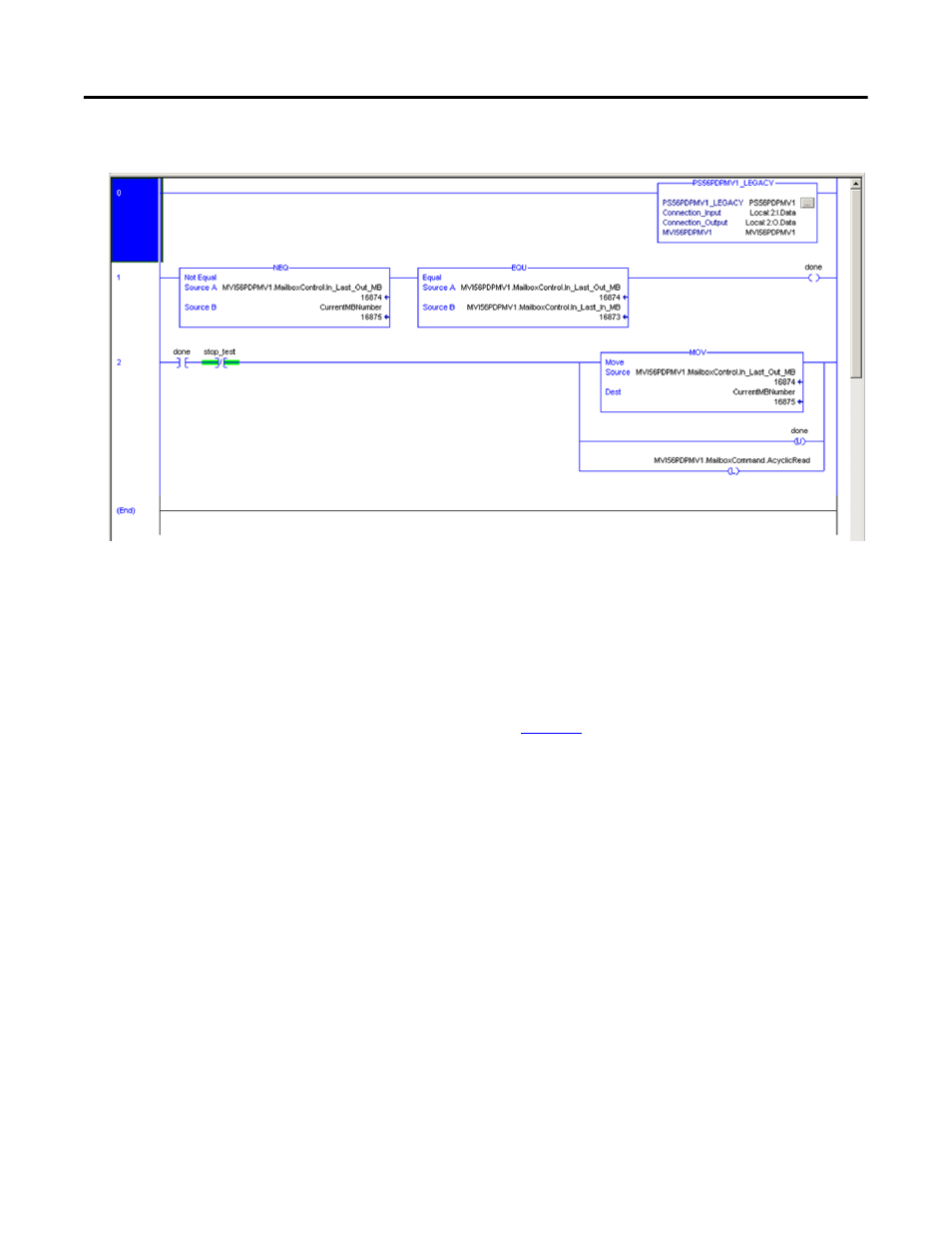
Figure 13 - Acyclic Class 1 Read Response Data using RSLogix Ladder Logic
Write Example for Drive Parameter 520 - [Max Fwd Speed]
To write to the PowerFlex 750-Series drive parameter 520 - [Max Fwd Speed]
using a Class 1 Acyclic Write Service, setup a ControlLogix controller (with a
MVI56-PDPMV1 Profibus Master). After the master is setup, the ControlLogix
tags must be populated with the correct slot and index addressing values to write
the parameter as shown in
.
Drive Parameter 520 - [Max Fwd Speed]:
• Slot No. = 0x00 + Quotient of (520 / 256) + 1 = 3
• Index No. = Remainder of (520 / 256) = 8
• Length in bytes of the value of the Parameter (32 bit floating point value) /
8 = 4
To test the Write Service, you may manually enter the values as shown below into
the MVI56-PDPMV1 controller scoped tags where a ProSoft MVI56-PDPMV1
Profibus master module has been installed in the backplane of the ControlLogix
controller rack.
• MVI56PDPMV1.Mailbox.AcyclicWrite.Out.SlotNumber = 3
• MVI56PDPMV1.Mailbox.AcyclicWrite.Out.SlaveAddress = 3
• MVI56PDPMV1.Mailbox.AcyclicWrite.Out.Length = 4
• MVI56PDPMV1.Mailbox.AcyclicWrite.Out.Index = 8
The data bytes to be written can be entered in the
MVI56PDPMV1.Mailbox.AcyclicWrite.Out.Data[] array, or the data may be