Elektrisches schaltbild, Schéma électrique, Electrical diagram – Rockwell Automation 100 G550...G860 Contactors User Manual
Page 7: Schema elettrico
7
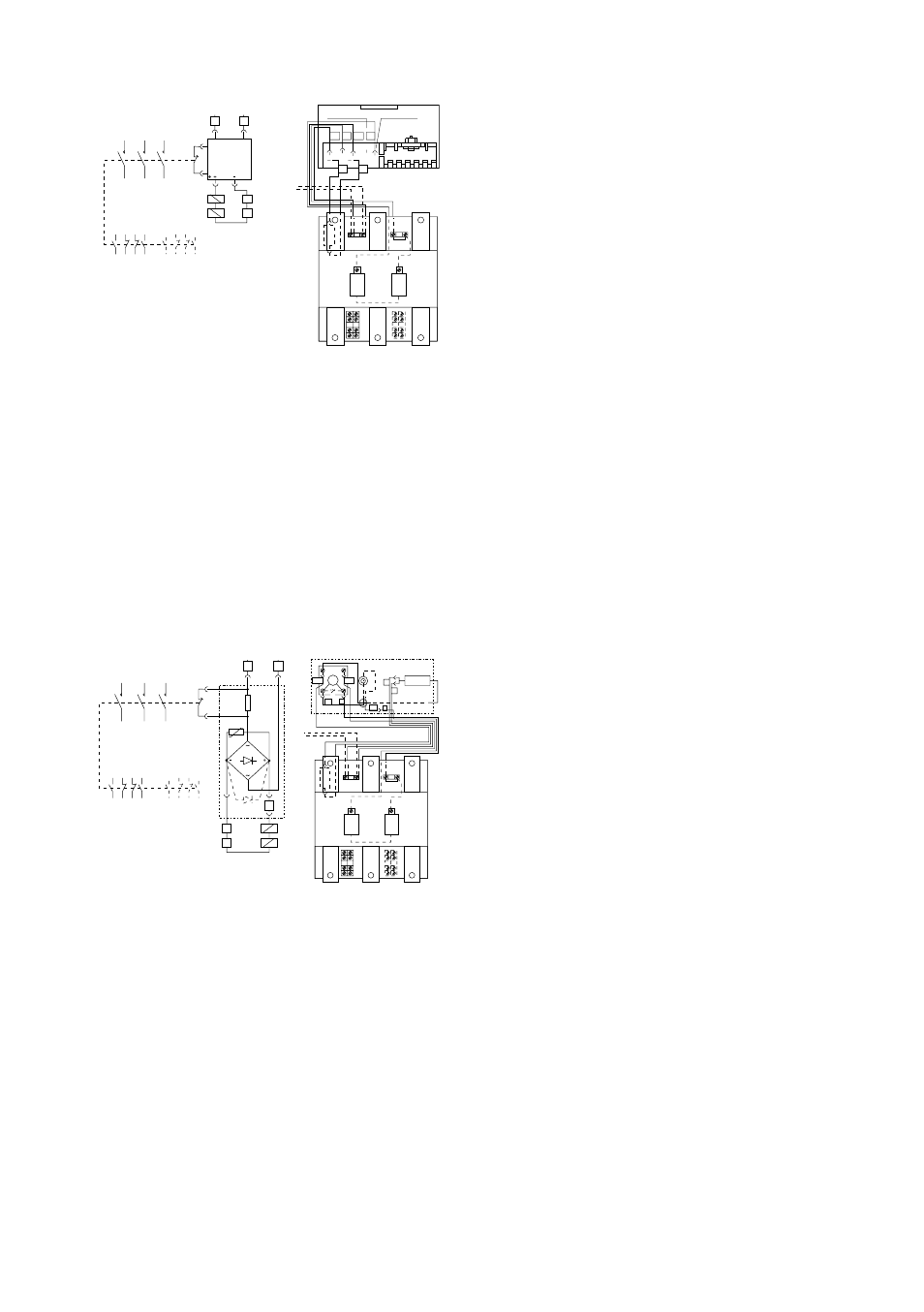
100-G550
C:
Schütz - Contacteur - Contactor - Contattore
C1:
Verzögerter «Ö» Kontakt EG01 - Contact «O» retardé EG01 - EG01
delayed NC contact - Contatto NC ritardato EG01
Y:
Hilfsschalter EF 22 - Contact auxiliaire EF 22 - EF 22 auxiliary contact
- Contatto ausiliario EF 22
C:
Schütz - Contacteur - Contactor - Contattore
C1:
Verzögerter «Ö» Kontakt EG01 - Contact «O» retardé EG01 - EG01
delayed NC contact - Contatto NC ritardato EG01
Y:
Hilfsschalter EF 22 - Contact auxiliare EF 22 - EF 22 auxiliary contact
- Contatto ausiliario EF 22
RT:
Gleichrichter - Redresseur - Rectifier - Raddrizzatore
VDR: Schutzvorrichtung (für Spannungen über 415 V werden 2 VDR in
Reihe geschaltet) -
Dispositif de protection (pour tensions supérieures à 415 V, il y a 2
VDR en série) -
Protection device (over 415 V there are two VDR in series) - Disposi-
tivo di protezione (per tensioni superiori a 415 V ci sono 2 VDR in
serie)
R:
Sparwiderstand - Résistance d'économie - Saving resistor - Resist-
enza di risparmio
Z:
Vorrichtung für kurzen Ausschaltverzug - Dispositif d'ouverture rapide
- Quick drop device - Dispositivo per rilascio pronto
D:
Diode (montiert bis 135 V Betätigungsspannung) - Diode (montée
pour tension de commande jusqu'à 135 V) - Diode (fitted up to 135 V
control voltage) - Diodo (montato solo per tensioni fino a 135 V)
D
Elektrisches Schaltbild
Das Schütz wird so ausgeliefert, dass eine normale Ausschaltzeit (150…200 ms)
erreicht wird. Ferner hat der Benützer jedoch die Möglichkeit, das Gerät auf eine
Ausschaltverzögerung (0,5…1 s) umzubauen. In dieser Konfiguration ist es im
geschlossenen Zustand geschützt gegen kurzzeitige Spannangsabsenkungen
und unsichere Kontakatabgabe in der Ansteuerung der Spule. Um das Schütz auf
Ausschaltverzögerung zu modifizieren, sind folgende Änderungen durchzuführen
(mit isoliertem Haupt- und Steuerstromkreis zu verrichten):
• Die Einspeiseabdeckung demontieren.
• 100-G550: Den Draht (+) von der Klemme « NORMAL DROP » lösen und an
der Klemme « DELAYED DROP » anschliessen.
• 100-G700/100-G860: Den Draht (Z+) vom positiven Pol des Gleichrichters
und den Draht (+) vom Draht (Z-) lösen; nachher den Draht (+) am positiven
Pol der Diode und den Draht (Z+) am Draht (Z-) wieder anschliessen. Nur bei
den Schützen mit 48V Steuerspannung muss auch die Diode « D » (welche
bereits mit dem positiven Pol der Gleichrichters verbunden ist) zwischen dem
+ und - Pol der Gleichrichterbrücke angeschlossen werden (zu diesem Zweck
Schutzchild der Diode abheben).
• Einspeiseabdeckung wieder montieren.
F
Schéma électrique
Le contacteur est livré déjà précâblé de façon à ce que son temps déclenchement
atteigne sa valeur normale (150…200 ms). Ultérieurement, l’utilisateur a la
possibilité de modifier l’appareil afin d’augmenter la temporisation à l’ouverture
(0,5…1 s). Dans ces conditions et en position fermée, le contacteur reste donc
insensible aux brèves chutes de tension sur le des bornes d’alimentation. Rèseau
et aux micro-coupures pouvant être provoquées par les contacts placés dans le
circuit de commande de la bobine. Pour modifier la temporisation au
déclenchement du contacteur, il faut effectuer les opérations suivantes (à
exécuter avec circuit principal et de commande isolés).
• Retirer le couvercle de protections des bornes d’alimentation.
• 100-G550: Déconnector le fil (+) de la borne « NORMAL DROP » et le
brancher sur la borne « DELAYED DROP ».
• 100-G700/100-G860: Déconnector le fil (Z+) du pôle positif du redresseur
ainsi que le fil (+) du fil (Z-); ensuite reconnecter le fil (+) sur le pôle positif de la
diode et raccorder le fil (Z+) au fil (Z-). Seulement dans le cas de contacteurs
avec une tension de commande de 48V, il faut également connecter la diode «
D » (laquelle est déjà raccordée sur le pôle positif du redresseur) entre les
pôles + et - du pont redresseur (pour cela, enlever le couvercle de protection
de la diode).
• Replacer le couvercle de protection de bornes d’alimentation.
EN
Electrical diagram
The contactor is normally wired so to have a normal dropout time (150…200 ms
abt). Furthermore, it features the ability to be arranged by the user with a delayed
dropout time (0,5…1 s abt). In this configuration, in a sealed condition, the
contactor is insensitive to short time fall and fluctuation of control voltage or
control device instability. To arrange the contactor for the delayed dropout the
following operations are necessary (to be performed with main and control circuit
insulated):
• Lift the feeder group cover.
• 100-G550: Disconnect wire (+) from «NORMAL DROP» terminal and connect
it to «DELAYED DROP» terminal.
• 100-G700/100-G860: Disconnect wire (Z+) from rectifier positive pole and
wire (+) from wire (Z-); Reconnect wire (+) to rectifier positive pole and wire
(Z+) to wire (Z-). For 48 V control voltage contactors only, connect also diode
« D » (which is already connected to rectifier positive pole) across + and -
poles of the rectifier bridge (remove the protective sheath of diode).
• Put back the feeder cover.
I
Schema elettrico
II contattore è normalmente collegato per avere un tempo di rilascio normale
(150…200 ms circa). E’inoltre possible predisporto, a cura dell’utilizzatore, con un
tempo di rilascio ritardo (0,5…1 s circa) ed in queste condizioni, quando è chiuso,
il contattore è insensibilie a brevi mancanze e fluttuazioni della tensione di
comanda o ad instabilità di dispositivi di contollo. Per predisporre il contattore
con il rilascio ritardato sono necessarie le seguenti operazioni (da eseguire con il
circuito principalee di comando isolati):
• Sollevare il coperchio alimentatore.
• 100-G550: scollegare il filo (+) dal terminale «NORMAL DROP» e collegarlo al
terminale «DELAYED DROP».
• 100-G700/100-G860: scollegare il filo (Z+) dal polo positivo del raddrizzatore
e il filo (+) dal filo (Z-). Solo per i contattori con tensione di comando 48 V,
collegare anche il diodo « D » (che è già precollegato al polo positivo del
raddrizzatore) tra i poli + e - del ponte raddrizzatore (rimuovere la guaina
protettiva).
• Risposizionare il coperchio alimentatore.
M1
M2
C
1
3
5
2
4
6
13 21 31 43
14 22 32 44
Y
Y
53 61 71 83
54 62 72 84
A1
A2
C1
C
C
1
3
5
2
4
6
C1
A1 A2
M1 M2
C
C
NC
NO
Y
NO
NC
Y
3
1
2
4
DELAYED DROP
NORMAL DROP
1AC
-
2AC
+
3
4
M1
M2
C
1
3
5
2
4
6
13 21 31 43
14 22 32 44
Y
Y
53 61 71 83
54 62 72 84
A1
A2
C1
VDR
1 RT
2
D
C
C
1
3
5
4
5
6
C1
A1 A2
M1 M2
C
C
NC
NO
Y
NO
NC
Y
1~ 2~
+
-
D
Z+
-
Z+
-
Z
R
R
R
Z
1AC
2AC
VDR
RT
100-G700/100-G860