Rockwell Automation 100 G550...G860 Contactors User Manual
Page 10
10
Set of 2 coils for 1 contactor
Set di 2 bobine per 1 contattore
EN
Coil Changing
The contactors are equipped with 2 coils series
connected and both coils have to be changed.
Ordering details for standard coils
Voltages
1
)
Type/
Pack
Ordering No.
Qty
V A.C.
V D.C.
110...120
100...110
TX 734
1 set
220...240
200...220
TX 747
1 set
380...415
345...380
TX 779
1 set
440...480
400...440
TX 780
1 set
110...120
100...110
TY 734
1 set
220...240
200...220
TY 747
1 set
380...415
345...380
TY 779
1 set
440...480
400...440
TY 780
1 set
1
) A.C. voltage values are valid for both 50 Hz and
60 Hz. Coils can be fed on A.C. or D.C.
Note: In case of a change in the control voltage
supply which would require a coil
changing, change the feeder group too.
Other voltages; please consult.
I
Cambio bobine
I contattori sono forniti con 2 bobine collegate in
serie. In caso di sostituzione è necessario
cambiarle entrambe.
Tabella bobine
Tensioni
1
)
Tipo/
Q.tà
N. di ordine
min.
V AC
V DC
indivis.
110...120 100...110
TX 734
1 set
220...240 200...220
TX 747 1
set
380...415 345...380
TX 779 1
set
440...480
400...440
TX 780
1 set
110...120
100...110
TY 734
1 set
220...240
200...220
TY 747
1 set
380...415
345...380
TY 779
1 set
440...480
400...440
TY 780
1 set
1
) I valori in AC sono validi a 50 Hz e 60 Hz. Le
bobine possono essere alimentate
indifferentemente in AC e DC.
Nota: Qualora si cambi la tensione d’alimenta-
zione è necessario sostituire le bobine e
l’alimentatore.
Altre tensioni: consultarci.
EN
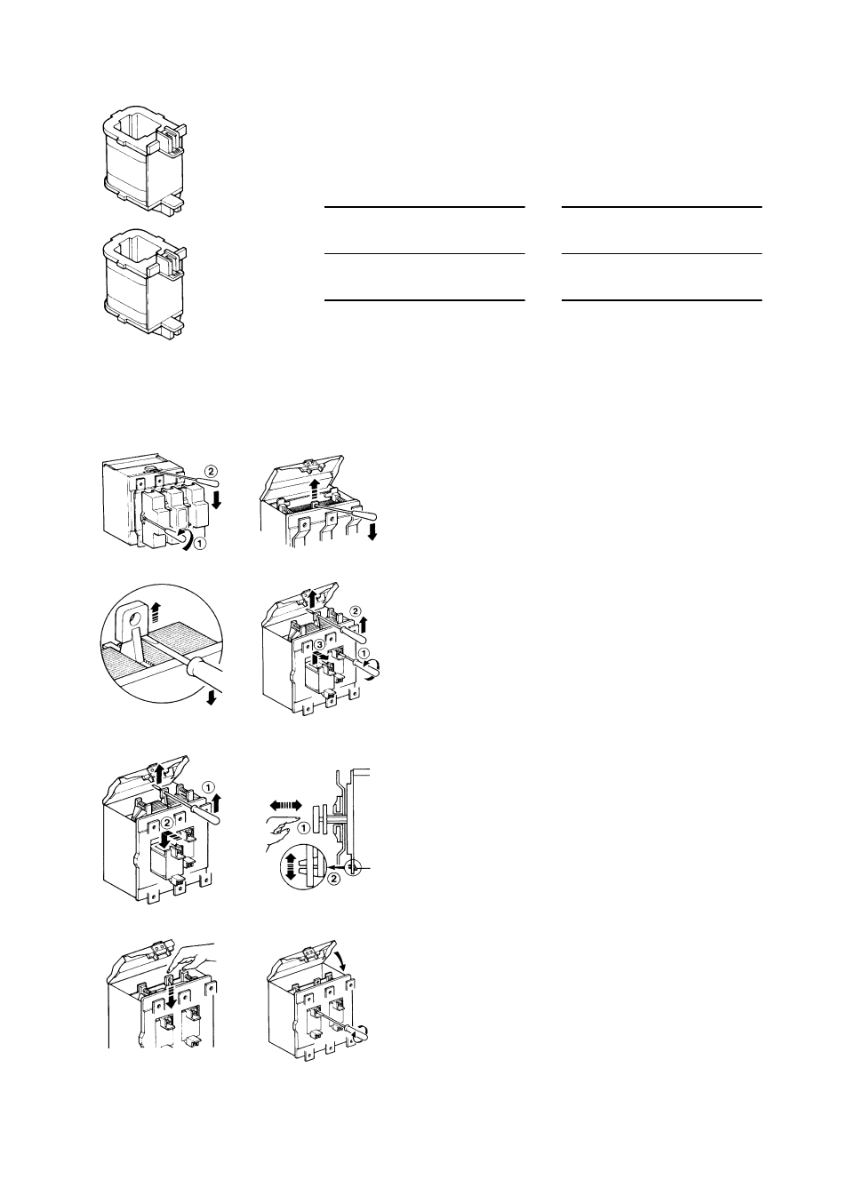
Instructions for changing the two coils
— Isolate main and control voltage.
— Take off the arc chute and lift the feeder cover (fig. 1 ).
— lnsert a screwdriver in the hole of plastic piece jointed to the upper core and
start lifting the core (fig. 2).
— Then lift the core completely acting upon the screwdriver (fig. 3).
— Unscrew the 4 coil fastening screws (fig. 4). By keeping the core lifted (fig. 4),
lift the coils by means of the proper front handles of about 5 mm and take them
from the contactor.
— Keeping the core lifted, fit the new coils (fig. 5).
— Before tightening the 4 coils fastening screws check that the lower core is
properly fitted in the coils. Press the main voltage contacts by hand to close
and check that the assembly moves freely (fig. 6). Otherwise it is necessary to
slightly move the lower core (Fig. 6).
— Refit the upper core into standard working position by pressing it downwards
(fig. 7).
— Tighten the 4 coil fastening screws (fig. 8).
Note: Before putting back the feeder group cover plus the arc chute and
energizing the contactor, check that the control voltage suits that one
indicated both on the coils and on the feeder group.
I
Istruzioni per la sostituzione delle bobine
— Togliere tensione al circuito di comando e di potenza.
— Togliere il parafiamme e sollevare il coperchio del modulo d'alimentazione
(fig. 1).
— Inserire un cacciavite nel foro della parte in plastica solidate con il nucleo
superiore ed iniziare a sollevare il nucleo (fig. 2).
— Sollevare poi completamente il nucleo facendo leva con il cacciavite come
indicato in fig. 3.
— Svitare le 4 viti di fissaggio e collegamento delle bobine (fig. 4). Tenendo
sollevato il nucleo (fig. 4) prendere le bobine dalle apposite appendici frontali e
alzarle di circa 5 mm; indi sfilarle dal contattore.
— Montare le nuove bobine (fig. 5).
— Prima di serrare le 4 viti di fissaggio delle bobine, assicurarsi che il nucleo
inferiore sia inserito correttamente nelle bobine stesse. A questo scopo,
spingere con le mani i contatti mobili nella direzione di chiusura e verificare
che l'equipaggio sia libero nel movimento (fig. 6). In caso contrario è
necessario smuovere leggermente il nucleo inferiore (fig. 6).
— Reinserire, spingendo verso il basso, il nucleo superiore nella normale
posizione di lavore (fig. 7).
— Bloccare le 4 viti di fissaggio delle bobine (fig. 8).
Nota: Prima di riposizionare il coperchio del modulo di alimentazione e
parafiamme e, prima di mettere il contattore sotto tensione, verificare che
la tensione di alimentazione sia compatibile con quella indicata sulle
bobine e sull'alimentatore.
Fig. 3
Fig. 4
Fig. 8
Fig. 7
Fig. 5
Fig. 6
Fig. 1
Fig. 2
Dismantling/Smontaggio
Mounting/Montaggio
100-G550
100-G700/100-G860