Rfid tags, Transceiver power up sequence – Rockwell Automation 56RF RFID System User Manual User Manual
Page 16
16
Rockwell Automation Publication 56RF-UM001A-EN-P - October 2011
Chapter 2
RFID Components
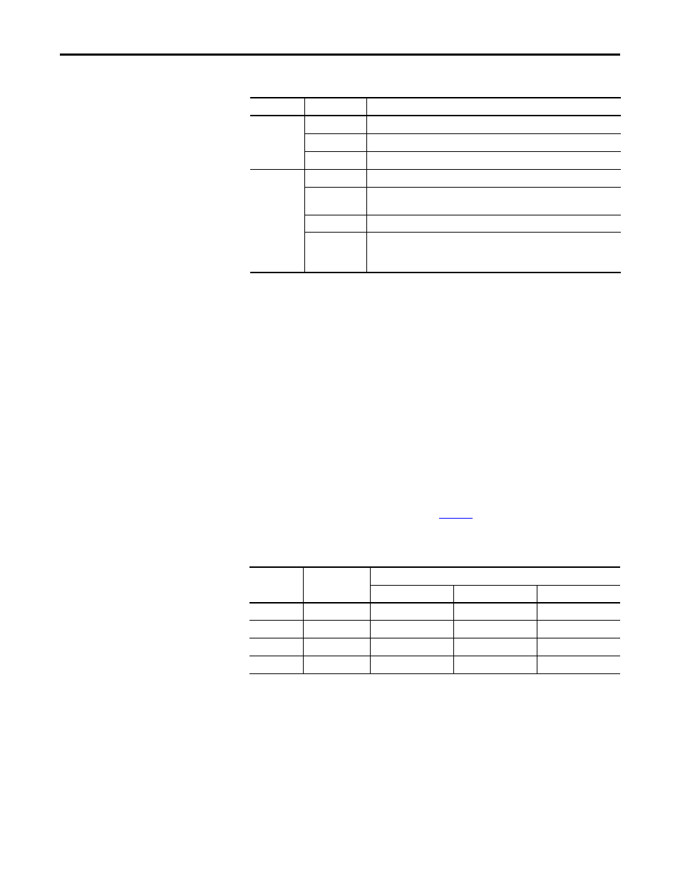
Table 3 - LEDs
Transceiver Power Up Sequence
1.
Both LEDs OFF.
2.
Power status turns green. R/W status turns green for 0.25 seconds.
3.
R/W status turns red for 0.25 seconds.
4.
R/W status turns off for 3…5 seconds.
5.
R/W status turns amber for 0.5 seconds.
6.
R/W status turns green.
RFID Tags
RF tags come in many shapes and sizes. In general, the bigger the tag, the longer
the sensing distance from the transceiver.
Table 4
summarizes the size of the
memory for each type of tag.
Table 4 - Memory
LED Name
LED State
Indicates
Module Status
Off
There is no power applied to the block.
Green
The block is operating in a normal condition.
Red
The transceiver has an unrecoverable fault; may need replacing.
Read/Write
Status
Off
There is no power applied to the device.
Green
The EIP interface block is communicating with the transceiver, but no tag is
present. No errors received.
Amber
A tag is present within the antenna field.
Red
A communication error has occurred. Examples are: bad read/write, corrupt CRC
Note: If a read/write command is not completed while the tag is within the
field, an error will occur.
Tag Type
Total Tag
Memory
User Memory
No. of Bytes
No. of Blocks
Bytes per Block
SLI
128 B
112 B
28
4
SLI-S
256 B
160 B
40
4
SLI-L
64 B
32 B
8
4
FRAM
2048 B
2 kB
250
8