Configuring and verifying key drive parameters – Rockwell Automation 20-COMM-L LonWorks Adapter User Manual
Page 22
2-6
Installing the Adapter
20-COMM-L LonWorks Adapter User Manual
Publication 20COMM-UM008B-EN-P
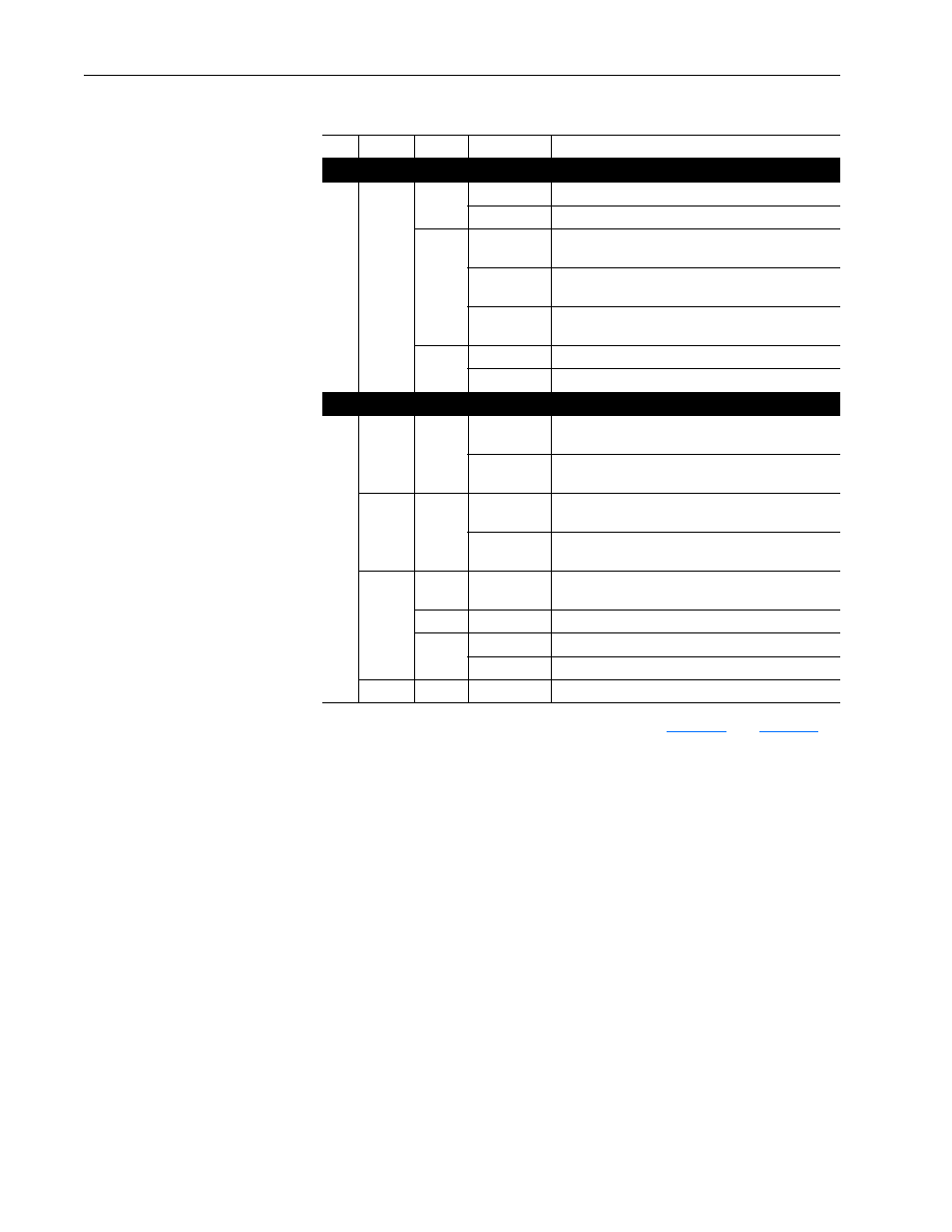
Table 2.A Drive and Adapter Start-Up Status Indications
For more details on status indicator operation, see
.
Configuring and Verifying Key Drive Parameters
The PowerFlex 7-Class drive can be separately configured for the control
and Reference functions in various combinations. For example, you could
set the drive to have its control come from a peripheral or terminal block
with the Reference coming from the network. Or you could set the drive to
have its control come from the network with the Reference coming from
another peripheral or terminal block. Or you could set the drive to have both
its control and Reference come from the network.
The following steps in this section assume that the drive will receive the
Logic Command and Reference from the network.
1. Use drive Parameter 090 - [Speed Ref A Sel] to set the drive speed
Reference to ‘22’ (DPI Port 5).
2. If hard-wired discrete digital inputs are not used to control the drive,
verify that unused digital input drive Parameters 361 - [Dig In1 Sel] and
362 - [Dig In2 Sel] are set to ‘0’ (Not Used).
Item Name
Color
State
Description
Drive STS Indicator
➊
STS
(Status)
Green
Flashing
Drive ready but not running, and no faults are present.
Steady
Drive running, no faults are present.
Yellow
Flashing,
drive stopped
An inhibit condition exists – the drive cannot be
started. Check drive Parameter 214 - [Start Inhibits].
Flashing,
drive running
An intermittent type 1 alarm condition is occurring.
Check drive Parameter 211 - [Drive Alarm 1].
Steady,
drive running
A continuous type 1 alarm condition exists. Check
drive Parameter 211 - [Drive Alarm 1].
Red
Flashing
A fault has occurred.
Steady
A non-resettable fault has occurred.
Adapter Status Indicators
➋
PORT
Green
Flashing
Normal operation. The adapter is establishing an I/O
connection to the drive. It will turn steady green or red.
Steady
Normal operation. The adapter is properly connected
and communicating with the drive.
MOD
Green
Flashing
Normal operation. The adapter is operating but is not
transferring I/O data to a controller.
Steady
Normal operation. The adapter is operating and
transferring I/O data to a controller.
NET A
Off
n/a
Normal operation. The adapter/drive node is
configured.
Red
Flashing
WINK command received.
Green
Flashing
The adapter/drive node is not configured.
Steady
The adapter/drive node has no application program.
NET B
—
—
Not used by LonWorks adapter.