Step 6: install the new mdi option board – Rockwell Automation 20D-MDI-C1 Multi-Device Interface Option Board for PowerFlex 700S Drives User Manual
Page 8
8
Multi-Device Interface Option Board for PowerFlex® 700S Drives
Step 6: Install the New MDI
Option Board
Phase I Drives
Important: Do not use a screwdriver to pry the P1 terminal block from the
circuit board. This may damage the terminal block.
Task
Description
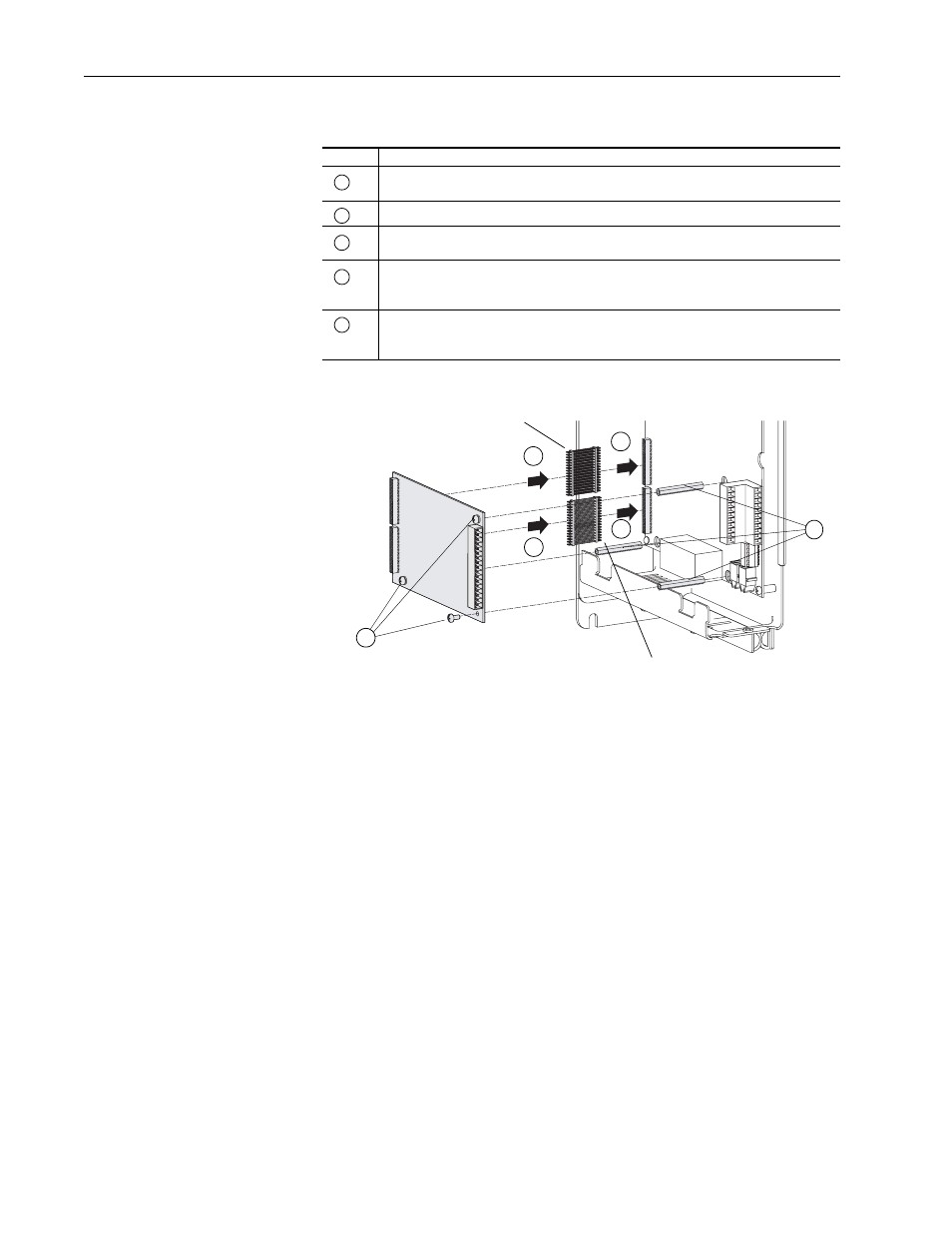
Remove terminal block P1 from the Resolver Feedback option board. It is much easier to
remove before the board is installed.
Install and tighten the stand-offs (min/max 7 in•lb / 10 in•lb).
Insert the short pins of the through-board pin connectors into the mating connectors on the
main Control board. The end with the short pins must plug into the main Control board.
Plug the mating connectors of the MDI Feedback option board onto the long pins of
through-board pin connectors. The end with the longer pins must plug into the MDI
Feedback option board.
Secure the board to the stand-offs, using the screw (supplied with this kit) and the captive
screws on the circuit board. Tighten the screws using a phillips screwdriver (min/max 6
in.•lb. / 8 in.•lb.).
A
B
C
D
E
The end with longer pins must
plug into the MDI option board
The end with short pins must
plug into the main control board
C
E
B
D
C
D
Note: Phase I shown.