Step 8: wire the mdi option board – Rockwell Automation 20D-MDI-C1 Multi-Device Interface Option Board for PowerFlex 700S Drives User Manual
Page 10
10
Multi-Device Interface Option Board for PowerFlex® 700S Drives
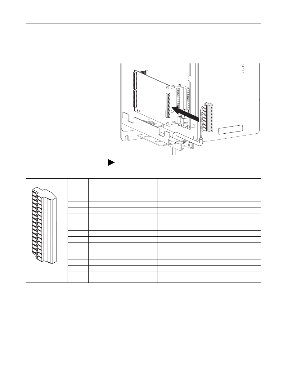
Step 8: Wire the MDI
Option Board
Terminal block P1 contains connection points for a linear sensor, rotary
encoder and registration strobe. This terminal block resides on the MDI
Option board
.
TIP: On Phase I drives, remember to route wires through the
sliding access panel at the bottom of the Control Assembly.
Terminal
Signal
Description
17
Rotary Encoder POWER COMMON
Power supply for Rotary Encoder interface
16
Rotary Encoder POWER
15
Rotary Encoder REFSIN
Positive Sine signal for Rotary Encoder interface
14
Rotary Encoder +SIN
Negative Sine signal for Rotary Encoder interface
13
Rotary Encoder REFCOS
Negative Cosine signal for Rotary Encoder interface
12
Rotary Encoder +COS
Positive Cosine signal for Rotary Encoder interface
11
Rotary Encoder DATA+ (RS485)
Positive DH485 terminal for Rotary Encoder interface
10
Rotary Encoder DATA- (RS485)
Negative DH485 terminal for Rotary Encoder interface
9
Linear Sensor CLOCK+
Positive Clock terminal for Linear Sensor interface
8
Linear Sensor CLOCK-
Negative Clock terminal for Linear Sensor interface
7
Linear Sensor DATA+
Positive SSI terminal for Linear Sensor interface
6
Linear Sensor DATA-
Negative SSI terminal for Linear Sensor interface
5
Rotary Encoder REGISTRATION+
Positive terminal for Rotary Encoder registration strobe
4
Rotary Encoder REGISTRATION-
Negative terminal for Rotary Encoder registration strobe
3
Linear Sensor REGISTRATION+
Positive terminal for Linear Sensor registration strobe
2
Linear Sensor REGISTRATION-
Negative terminal for Linear Sensor registration strobe
1
CHASSIS GND
Connection point for cable shields
1
5
4
3
2
8
7
6
91
3
12
11
10
16
15
14
17