Tools that you need, What you need to do, Step 1: remove power from the drive – Rockwell Automation 20D-MDI-C1 Multi-Device Interface Option Board for PowerFlex 700S Drives User Manual
Page 2
2
Multi-Device Interface Option Board for PowerFlex® 700S Drives
Tools That You Need
•
Phillips
®
screwdriver for M3 screws
•
POZIDRIV
®
screwdriver for M4 screws (for high power drives only)
•
Nut driver or wrench for M3 hex nut
•
Nut driver or wrench for M5 hex nut
Phillips
®
is a registered trademark of Phillips Screw Company
POZIDRIV
®
is a registered trademark of Phillips Screw Company
What You Need to Do
To remove the MDI option board from the PowerFlex 700S drive:
❐ Step 1: Remove power from drive
❐ Step 2: Remove drive cover(s)
❐ Step 3: Remove Control Assembly from Phase I drive (if necessary)
❐ Step 4: Remove Phase II Control Cassette covers
❐ Step 5: Remove existing MDI option board
To install the new MDI option board on the PowerFlex 700S drive:
❐ Step 6: Install new MDI option board
❐ Step 7: Install Control Assembly on Phase I drive (if removed in step
3)
❐ Step 8: Wire MDI option board
❐ Step 9: Install Phase II control cassette covers
❐ Step 10: Document revision changes
❐ Step 11: Install drive cover(s)
To return replaced MDI option board, use packing material from the new
MDI option board.
Step 1: Remove Power
from the Drive
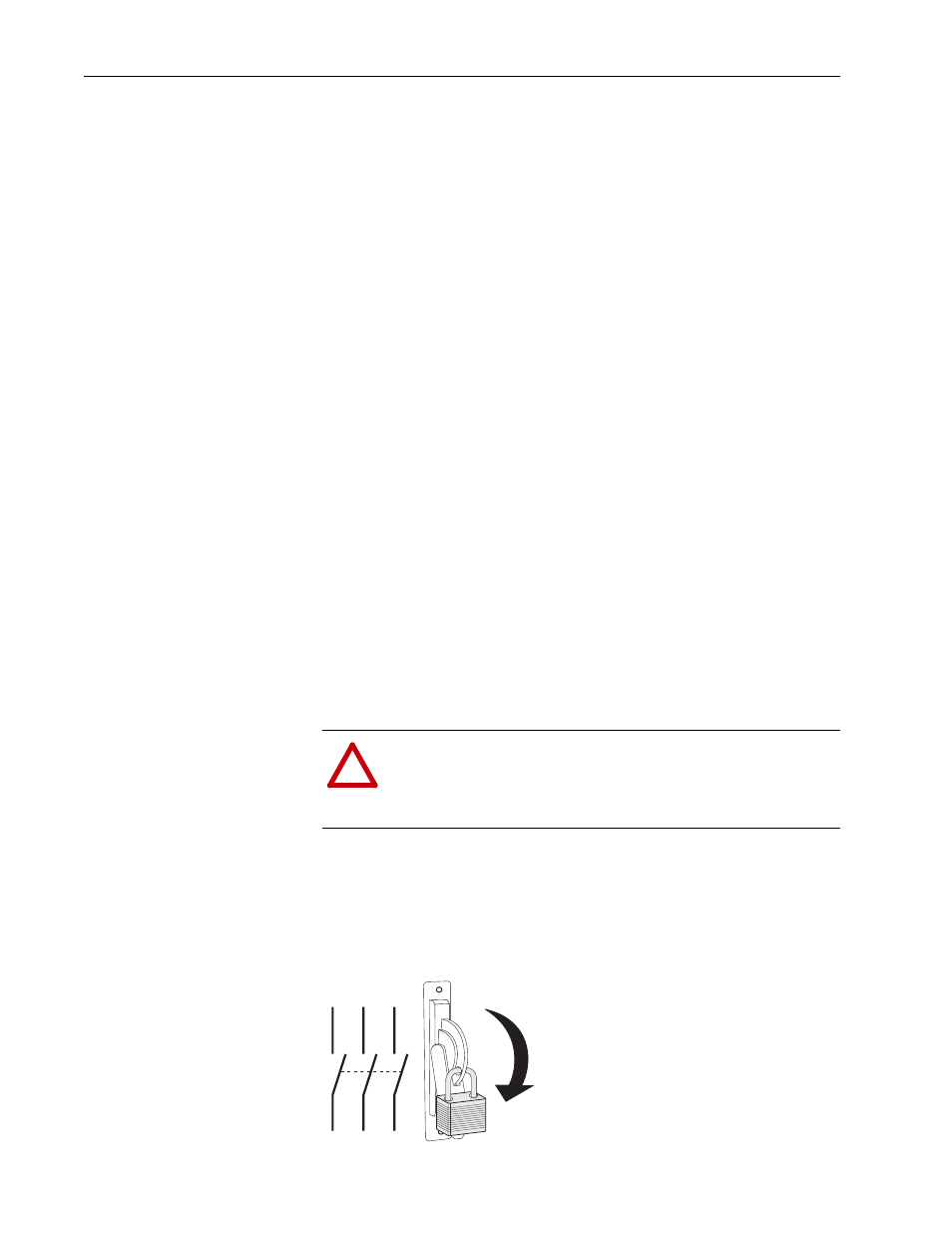
1. Turn off and lock out input power. Wait five minutes.
2. Verify that there is no voltage at the drive’s input power terminals.
3. Measure the DC bus voltage at the DC+ & DC- terminals on the Power
Terminal Block. The voltage must be zero.
!
ATTENTION: To avoid an electric shock hazard, verify that
the voltage on the bus capacitors has discharged before
performing any work on the drive. Measure the DC bus voltage
at the +DC & –DC terminals of the Power Terminal Block (DC+
& DC- in high power drives). The voltage must be zero.
L1
L2
L3
O
I