System schematic – Yamato Scientific WR600S AutoPure User Manual
Page 3
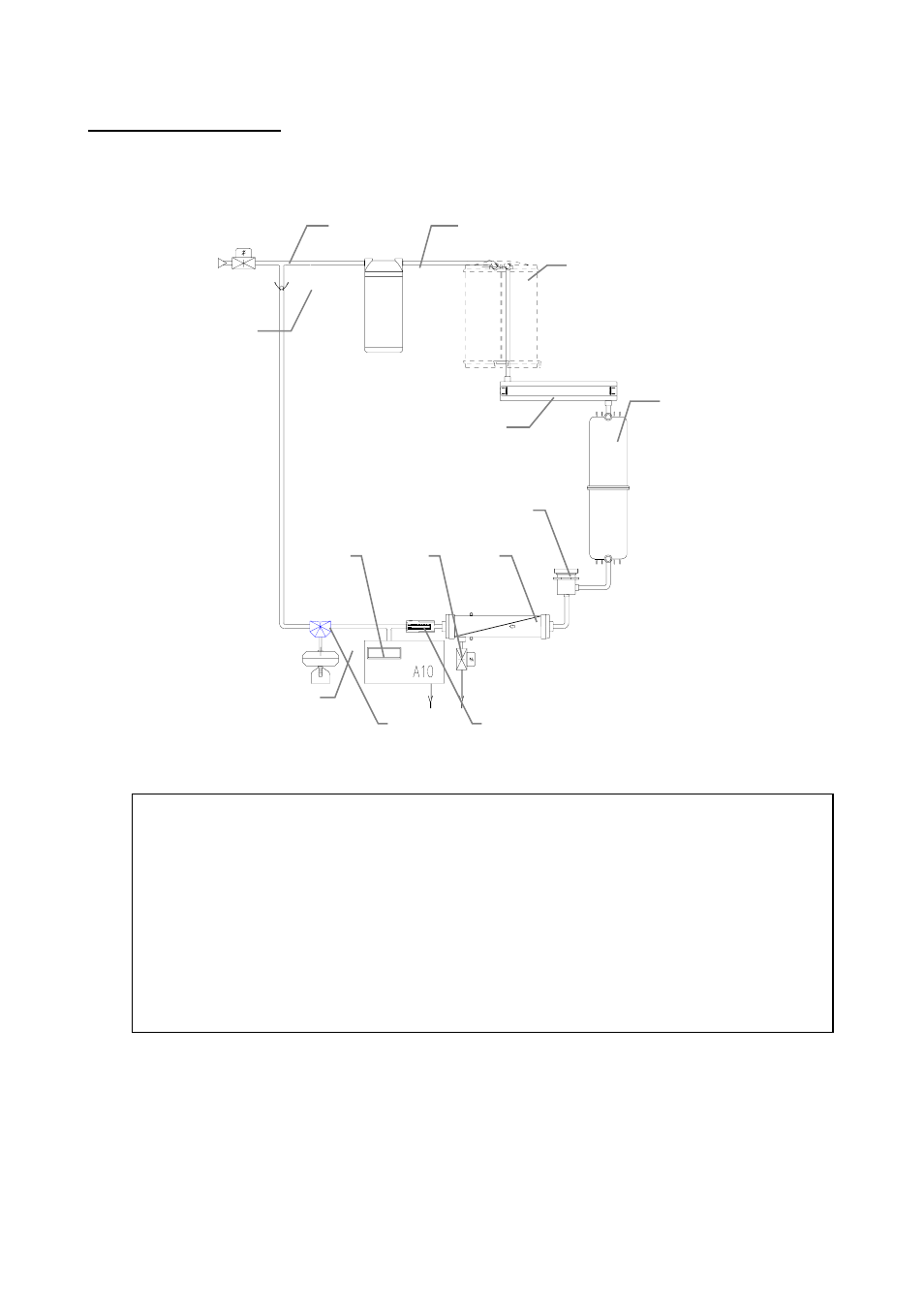
System Schematic
The water flow schematic of a Autopure WR600 system is shown below. Only the main components are shown
.
Inlet solenoid valve
1
Pump 2
Q-Gard Pack (presence depends upon the type of feedwater)
3
QUANTUM cartridge
4
Resistivity cell
5
Point of use with dispensing valve
6
MILLIPAK 40 final filter
7
Check valve
8
UV light
9
Sanitisation port used to introduce chemical sanitants to UF module
10
Ultrafiltration cartridge
11
UF cartridge reject solenoid valve
12
A-10 TOC monitor
13
1
9
4
2
3
6
7
10
11
12
13
8
5
This manual is related to the following products: