Burnham SCG 1100-H4 User Manual
Page 32
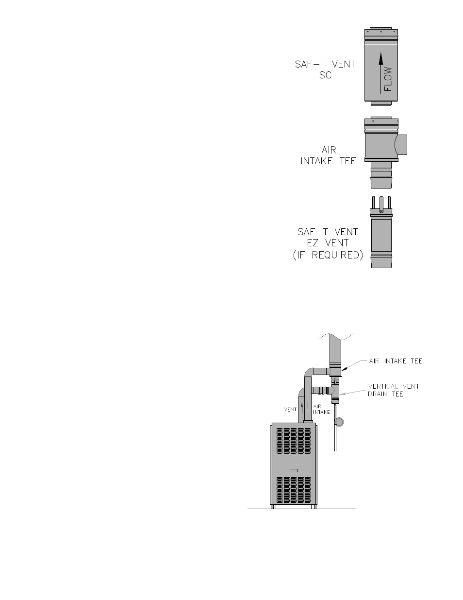
9. Air Intake Connections for Direct Vent and Sealed
Combustion Appliances*:
The Air Intake Tee may be used on approved direct vent
and sealed combustion appliances that have separate (non-
concentric) air intake and flue exhaust collars. The male end
of the tee connects to EZ Seal appliance adapters and the tee
takeoff/snout connects to the appliance air intake.
• Insert the male end of the Air Intake Tee into the female
end of the EZ Seal vent section or appliance adapter and
complete the ring and tab connection.
• Insert the male end of the next SC section into the
female end of the Air Intake Tee and secure as described
elsewhere in this manual.
• Connect the tee takeoff to the appliance combustion air
inlet using appropriate hose or pipe.
* Direct Vent Appliances are constructed and installed so that
all air for combustion is supplied directly from the outside
atmosphere. The passage for the combustion air is allowed
a small amount of leakage in the building environment. No
special installation considerations are required to use Saf-T
Vent SC on Direct Vent appliances unless specified by the
appliance manufacturer. Sealed Combustion appliances are
similar to Direct Vent except the combustion air passage must
be sealed to prevent leakage within the building envelope.
When Saf-T Vent SC is used on approved Sealed Combustion
appliances the joints of the outer jacket must be sealed with
a foil tape (example: 3M 425), or approved silicone sealant
(example: Dow Corning 732).
10. Condensate Drains:
When An Internal Condensate Drain is NOT Part of the
Appliance:
• A Saf-T Vent SC In-Line Drain Section is strongly
recommended. Install this drain fitting as close to the
appliance flue collar as possible.
• A condensate drain is required for every 30 feet of
horizontal vent and at/near the bottom of a vertical stack.
• Use the In-Line Drain Section for a straight horizontal or
vertical run. When used horizontally, rotate the fitting so that
the drain tube is as vertical as possible.
• A Condensate Drain Tube Kit is available to direct the condensate
to an appropriate location, i.e. floor drain or vented sanitary
sewer connection. A trap loop must be formed into the drain
hose and must be a diameter that is at least four (4) times the
appliance’s rated stack pressure in inches of water column or 3
inches, whichever is greater. Secure the loop with a cable tie.
Prior to final assembly the trap loop must be ‘primed’ by pouring
a small quantity of water into the drain hose. Inspect at least
annually to verify the trap is ‘primed’.
• Follow all local and national codes and regulations for the
draining of acidic condensate.
• In cold climates do not install a condensate drain on the exterior
of the building. Doing so may result in dangerous icy conditions
on surfaces near the drain and may cause damage to the vent
system and/or the building exterior.