Precision Turbo and Engine BigStuff3 GEN3 PRO SEFI (LS1) System Hardware & BigComm Software User Manual
Page 37
BigStuff3 Pro SEFI System (LS1)
Version 1.0
36
Setting the LS1 Crank Reference
Now that TDC for the number one (1) cylinder (compression) has been determined, the next step
is to determine the 1
st
• Roll the crankshaft back 30
crank falling edge after the cam falling edge. A voltmeter is required to
perform this task. A crankshaft degree wheel is also recommended.
The following paragraphs outline the process steps.
o
Before Top Dead Center (BTDC). A crankshaft degree
wheel or balancer timing tape will help expedite the process. If neither is available, the
following formula can be used to measure the distance, on the surface of the balancer that
equals 30
o
Multiply the diameter of the balancer by 3.14. Divide the result by 360, and
then multiply by 30 (representing the 30
.
o
).
Example based on a 7” balancer: 7 x 3.14= 21.98. 21.98/360= .06105” (per
degree). .06105” x 30
o
=1.8316”. From the TDC mark on the balancer,
measure forward (clockwise) about 1-13/16” and make a mark, which will
represent 30
o
• Next, make sure the main wire harness camshaft connector is attached to the stock LS1
camshaft sensor and the main wire harness Switched 12-Volt wire is connected and
“live”. The main harness battery connections also must be in place.
BTDC.
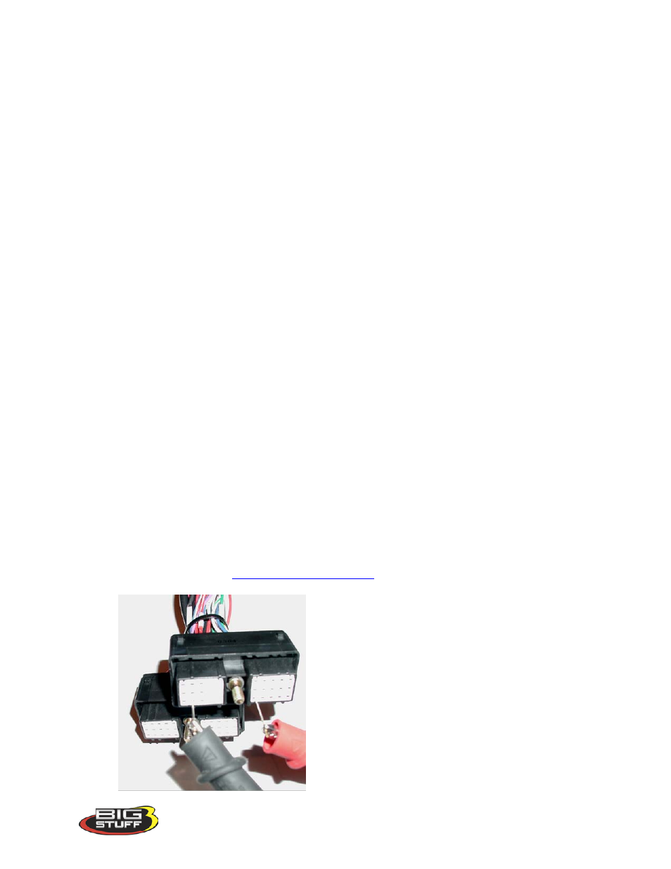
• Attach the Voltmeter’s red lead to the main wire harness terminal E3 (Signal) and the
Voltmeter’s black lead to the main wire harness terminal J2 (Gnd). These terminals are
attached to wires routed back to the camshaft sensor. The easiest way to accomplish this
is to insert sewing needles between the Voltmeter’s positive and negative alligator
clamps, and then push them into the aforementioned header connector terminals.
Note:
Make sure the probes (sewing needles) inserted into the E3 and J2 terminals do not
touch each other. Doing so will damage the main wire harness!
Note: It is important to use probes with tapered tips (like sewing needles) rather than
blunt tipped probes (like paper clips) to avoid damaging the main harness header
connector terminals.