Power & motor connections, Usb power, Motors – Pololu Orangutan SVP User Manual
Page 8
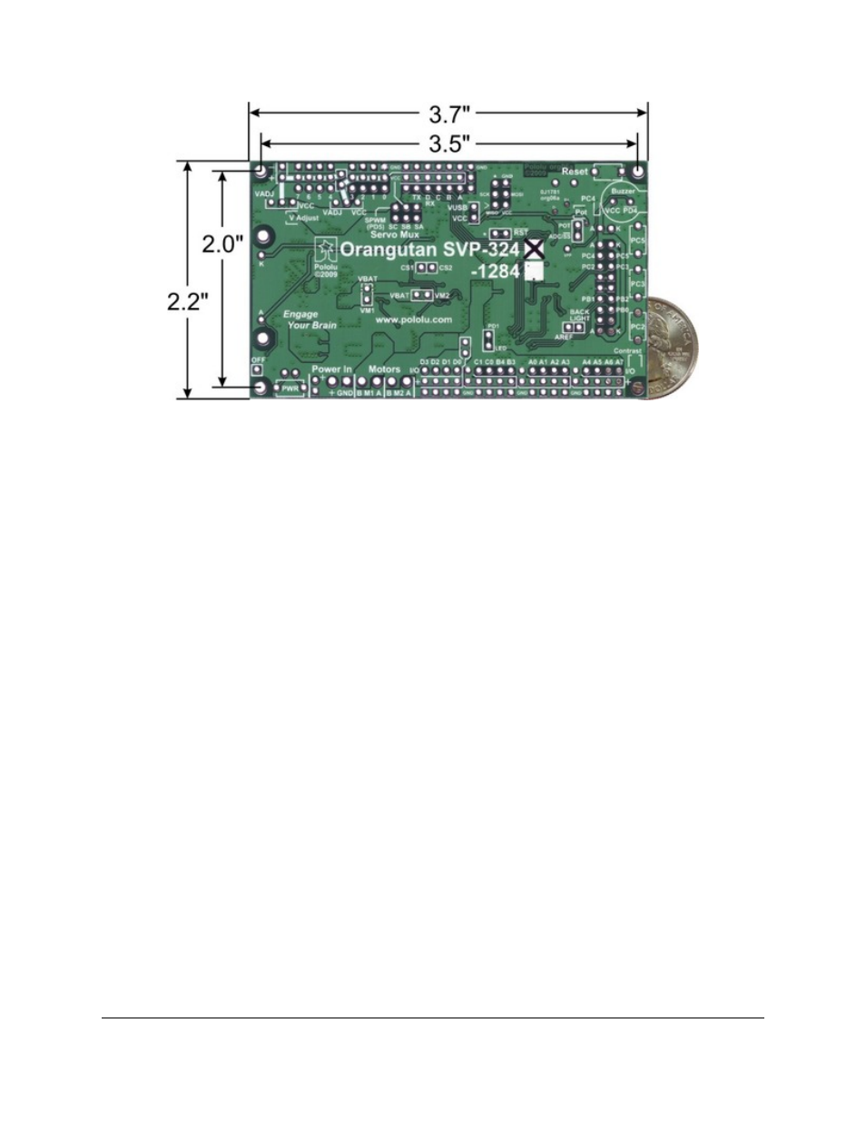
Orangutan SVP-324 with dimensions.
Power & Motor Connections
Power for the Orangutan SVP should be connected to the positive (+) and ground (GND) terminals near the words
“Power In” on the board. The input voltage (VIN) of the power supply should be 6 – 13.5 V, from which the on-
board regulator generates the 5 V supply (VCC) that is used to power the logic.
The Orangutan SVP has one TB6612FNG motor driver for each motor output. Each motor driver can deliver a
continuous 2 A, and can briefly deliver up to 6 A. If you are not taking extra steps to keep the motor driver cool,
such as using a heat sink, exceeding this continuous current rating for too long will cause the motor driver to heat
up and trigger its built-in thermal shutdown.
By default, the motor drivers are powered from VBAT, which refers to the input voltage (VIN) after passing
through reverse protection and the power switch circuit. However, you can disconnect VBAT from the motor
drivers by cutting the labeled traces on the bottom of the board (VBAT-VM1 and VBAT-VM2). This allows you
to connect some other power supply to the motor drivers, such as VADJ (see below). The motor drivers have an
operating range of 4.5 – 13.5 V, so your power supply should be in that range, and should be capable of supplying
all the current that your motors might draw.
USB Power
When connected to a computer, the USB connection provides a 5 V power supply. If an external power supply is
present, the unit will run off of the external supply and not draw any power from USB. If only the USB power is
present, then by default the auxiliary processor will be powered from USB, but the AVR and the VCC power pins
on the board will not be powered. An option is available for powering the entire board from USB. See
for more information.
Motors
The motor drivers are controlled by two of the AVR’s hardware PWM outputs from eight-bit Timer2 for speed
control, along with two digital outputs for direction control. This lets you achieve variable motor speeds using
hardware PWMs rather than processor-intensive software PWMs on the motor control lines. You can control the
motors using the functions in the
section of the Pololu AVR
C/C++ Library.
Pololu Orangutan SVP User's Guide
© 2001–2012 Pololu Corporation
4. Module Pinout and Components
Page 8 of 37