Power button, Power input, Motor outputs – Pololu Orangutan SVP User Manual
Page 21: User i/o blocks, Backlight and aref header, Lcd connector
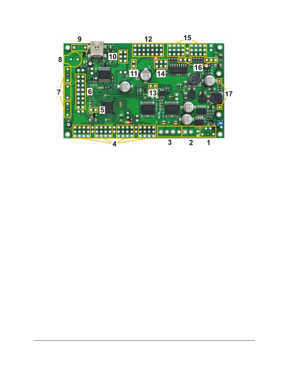
Orangutan SVP kit PCB showing possible locations for included buzzer,
pushbuttons, headers, and terminal blocks.
1. Power button
To turn on your the AVR, you need to connect a power button (or a jumper at location 11). The Orangutan SVP
PCB has two parallel sets of holes for the power button. You can solder a pushbutton between the wider set of
holes, and/or you can make your own connection to the narrower of holes using an included 1×2 header or direct
soldering. If the Orangutan is not easily accessible inside your robot, this allows you to install a momentary power
switch in a more convenient location.
2. Power input
There are two parallel connection points provided for the 6–13.5V power input. You can install a 3.5mm terminal
block on the large holes to accommodate large wires. You can also install a 1×2 male header on the smaller holes
and plug a
directly in to it.
3. Motor outputs
You can install two 3.5mm terminal blocks to accommodate your motor leads.
4. User I/O blocks
The AVR user I/O pins are divided in to four blocks. The kit comes with enough 3×4 headers so that you can
choose for each block whether to make its pins female or male. You can also mix the genders together within one
block using the other included headers.
5. Backlight and AREF header
If you want to be able to turn your LCD’s backlight off or use an external voltage reference source, you may want
to solder a 1×2 header on to this location.
6. LCD connector
The pins in the LCD connector area are arranged so that the AVR can control an LCD using the standard 4-bit
HD44780 protocol and optionally power an LCD backlight. On the assembled (non-kit) version of the Orangutan
Pololu Orangutan SVP User's Guide
© 2001–2012 Pololu Corporation
5. Getting Started
Page 21 of 37