Module pinout and components – Pololu Orangutan SVP User Manual
Page 7
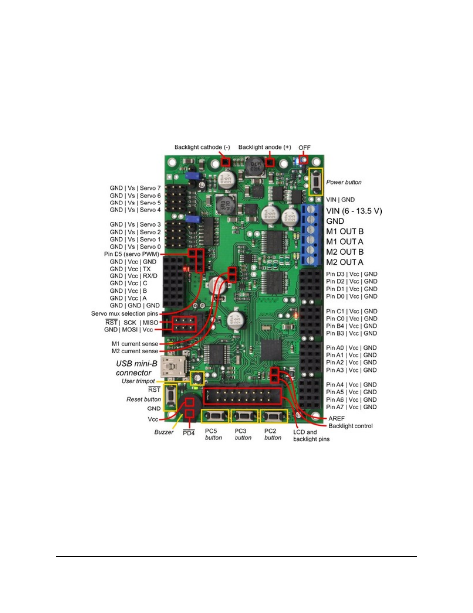
4. Module Pinout and Components
The Orangutan SVP contains a programmable AVR ATmega324PA or ATmega1284P microcontroller connected
to two motor drivers for direct control of two DC motors, a 16×2 character LCD, a buzzer, three user pushbuttons,
two user LEDs, and a demultiplexer for servo control. The AVR is also connected to an auxiliary processor (a
PIC18F14K50) that provides access to the battery voltage, a 10 kilo-ohm user trimmer potentiometer, and four
additional input lines. The auxiliary processor also serves as a programmer for the main processor, meaning that
an external programmer is not required, but you can use one if you want to. The auxiliary processor also allows
for USB communication between the AVR and a personal computer, and acts as a USB-to-serial converter.
Orangutan SVP fully assembled PCB with pins labeled.
These and the rest of the main features of the module are labeled in the picture above and in more detail
in
the
(82k pdf). Most of the connection points are also indicated on the
silkscreen on the back side of the PCB, as shown below. The overall unit dimensions are 3.7" × 2.2", and four
0.086" mounting holes, suitable for #2 screws, are located 0.1" from the corners of the board.
Pololu Orangutan SVP User's Guide
© 2001–2012 Pololu Corporation
4. Module Pinout and Components
Page 7 of 37