Leds – Pololu Orangutan SVP User Manual
Page 12
LEDs
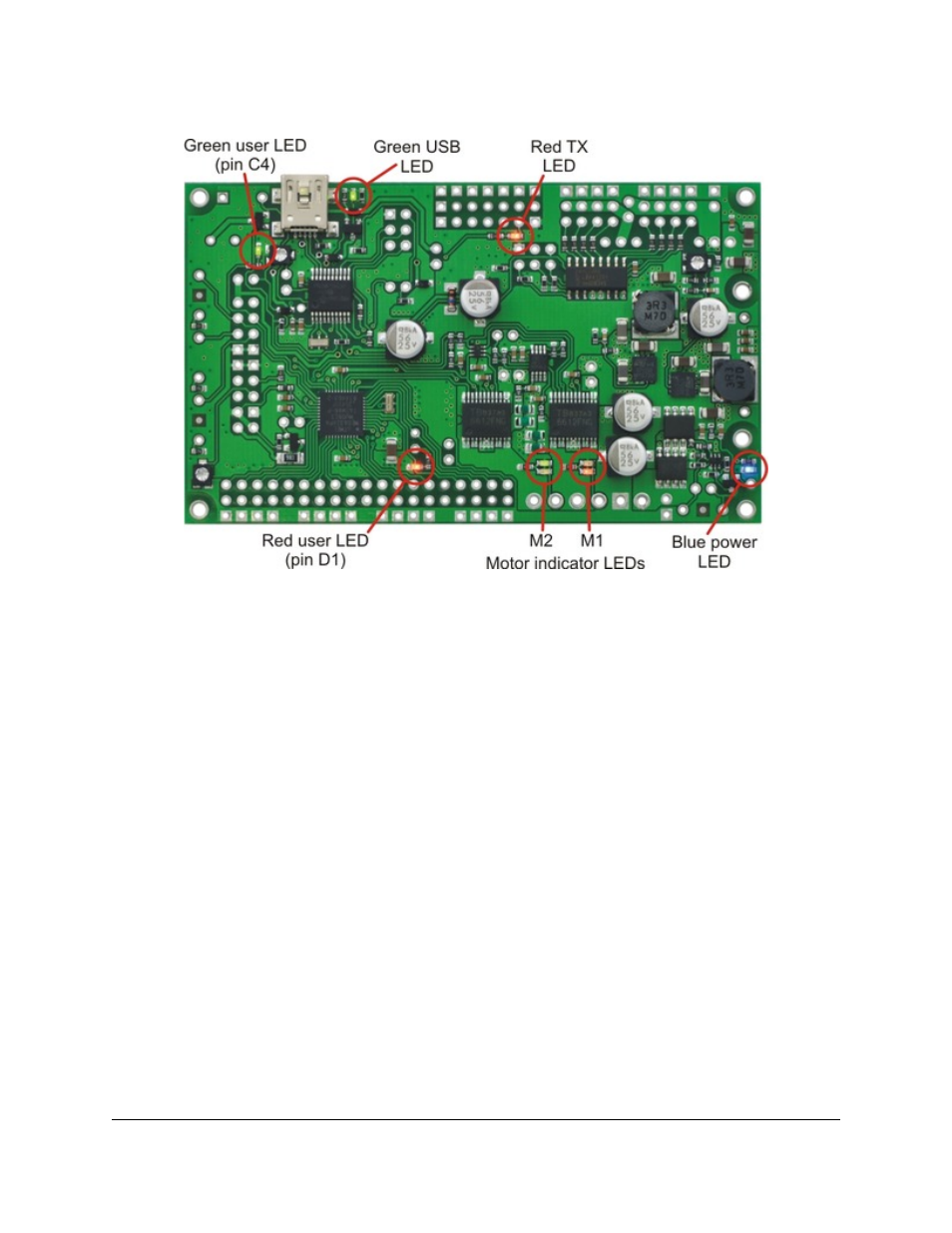
Orangutan SVP LEDs.
The Orangutan SVP comes with 9 LEDs:
• A
blue
power LED is located next to the power button.
• There are four motor indicator LEDs located near the motor outputs. A
green
LED lit indicates that the
corresponding motor is being driven “forward” (the voltage on output B is higher than the voltage on A).
A
red
LED indicates that the corresponding motor is being driven in “reverse” (the voltage on output B is
lower than the voltage on output A).
• A
red
user LED is located near the AVR I/O banks. The LED is connected to the user I/O line PD1. It will
light if you set PD1 as a low output. Since PD1 is the serial transmit line for UART0 (TXD0), the LED will
flicker whenever serial data is being transmitted from the AVR. The LED can be disconnected from PD1 by
cutting a labeled trace (PD1-LED) on the bottom of the board.
• A
green
user LED is located between the trimpot and the buzzer. It will light if you set PC4 as a high
output. Note that PC4 is also used as an LCD data line, so you will see the green LED flicker when you
update the LCD.
• Another
green
LED is located near the USB connector. This LED is controlled by the auxiliary processor
and indicates the status of the USB connection. When the USB is disconnected, or the device is in the USB
Suspend state (because the computer went to sleep), the green LED is off. When you connect the device
to a computer via USB, the green LED will start blinking slowly. The blinking continues until it receives a
particular message from the computer indicating that the drivers are installed correctly. After the programmer
gets this message, the green LED will be on, but it will flicker briefly when there is USB activity.
• Another
red
LED is located near the header for the auxiliary processor’s TX line. This LED is tied to
the TX line, so it will flicker whenever the auxiliary processor is transmitting TTL-level serial bytes from
the computer. This LED will also blink when the auxiliary processor powers up to indicate bad startup
conditions. Two blinks indicates that a brown-out reset was triggered: the processor’s VDD dropped below
Pololu Orangutan SVP User's Guide
© 2001–2012 Pololu Corporation
4. Module Pinout and Components
Page 12 of 37