2 board-mounted bank 2 settings, Board-mounted bank 2 settings, When multiple management modules such as the – Omnitron Systems Technology Converter GXTM User Manual User Manual
Page 9: Iconverter
3.2.2
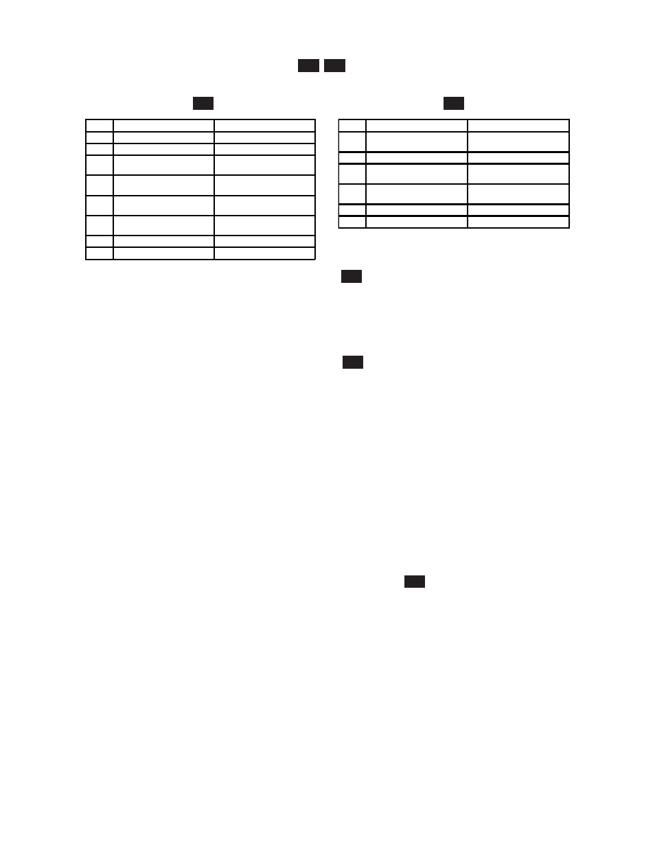
Board-Mounted Bank 2 Settings
PI
SA
DIP-switch Bank 2 is available on both the plug-in and standalone modules.
PI
SA
Switch
Left (Factory Default)
Right
SW1 A-DS: Port A Disabled
A-EN: Port A Enabled
SW2 B-DS: Port B Disabled
B-EN: Port B Enabled
SW3 Off:
Pause Disable
Pause:
Pause Enable
SW4 M/SL:
Master/Slave Auto-Select
SL:
Slave-Mode Only
SW5 Auto:
UTP Auto Crossover
Man:
UTP Manual Crossover
SW6 =:
Manual UTP Straight-Through
X:
Manual UTP Crossover
SW7 Reserved
Reserved
SW8 Reserved
Reserved
Switch
Down (Factory Default)
Up
SW3 Off:
Pause Disable
Pause:
Pause Enable
SW4 Reserved
Reserved
SW5 Auto:
UTP Auto Crossover
Man:
UTP Manual Crossover
SW6 =:
Manual UTP Straight-Through
X:
Manual UTP Crossover
SW7 Reserved
Reserved
SW8 Reserved
Reserved
3.2.2.1
SW1 - Backplane Port A Enabled “A-DS/A-EN”
PI
When the DIP-switch is in the Left “A-DS” position (factory default), Backplane Port A of the GX/TM is
isolated from the chassis Backplane. When the DIP-switch is in the Right “A-EN” position, Backplane
Port A of the GX/TM is enabled. This port allows Ethernet Backplane connectivity to an adjacent module
via the chassis Backplane Port A. See the backplane illustrations in Section 2.1.3.
3.2.2.2
SW2 - Backplane Port B Enabled “B-DS/B-EN”
PI
When the DIP-switch is in the Left “B-DS” position (factory default), Backplane Port B is isolated from the
chassis Backplane. When the DIP-switch is in the Right “B-EN” position, Backplane Port B is enabled.
This port allows Ethernet Backplane connectivity to an adjacent module via the chassis Backplane Port B.
See the backplane illustrations in Section 2.1.3.
3.2.2.3
SW3 - Pause Disable/Enable “Off/Pause”
When the UTP port is operating in Auto-Negotiation mode, it advertises for Pause based on the Pause
Disable/Enable “Off/Pause” DIP-Switch setting. Setting the Pause DIP-switch to the Pause Disable “Off”
position (factory default) forces the UTP port to negotiate to No Pause. Setting this DIP-switch to the Pause
Enable “Pause” position allows the UTP port to negotiate to Symmetrical Pause, Asymmetrical Pause or
No Pause mode. When the UTP port is operating in Manual mode, Pause is disabled.
NOTE: When the Fiber optic port operates in Auto-Negotiation mode, the port advertises for Pause.
When the Fiber optic port operates in Manual mode, Pause is disabled.
3.2.2.4
SW4 - Master/Slave Auto-Select and Slave-Only “M/SL / SL
PI
When multiple management modules such as the
iConverter
NMM and the GX/TM (or multiple self-managed
modules such as the 10/100M) are installed in the same chassis, only one management module can act as
the chassis master. The master management module has the ability to make changes to the settings of the
other modules in the chassis, while the slave management modules cannot make the changes. If an NMM
is installed in the chassis, the NMM will always be the master, otherwise the lowest slot number with a
management module installed will become chassis master.
When this DIP-switch is in the Left “M/SL” position (factory default), the assignment of mastership is
automatically negotiated by the installed management modules. To designate a specific management module
as the master when no NMM is installed in the chassis, set the DIP-switch on the master module to the Left
“M/SL” position, and set the other installed management modules’ DIP-switches to the Right “SL” position
to enable Slave-Only mode.
Only the chassis master can change configuration settings of other modules.
Page 9