MTS SWIFT 10 ATV Sensor User Manual
Page 71
Road and Track Vehicles
SWIFT 10 ATV Sensors
Installing the Transducer
71
E.
Attach the transducer output cable to the slip ring encoder connector
and the J3 Transducer connector on the TI box.
Secure the cable along its length so that it will not become damaged
during testing. (For example tape it to the anti-rotate tube to prevent it
from getting caught in the tire tread.) Leave enough slack in the cable
to allow for the full range of wheel travel (jounce and steer).
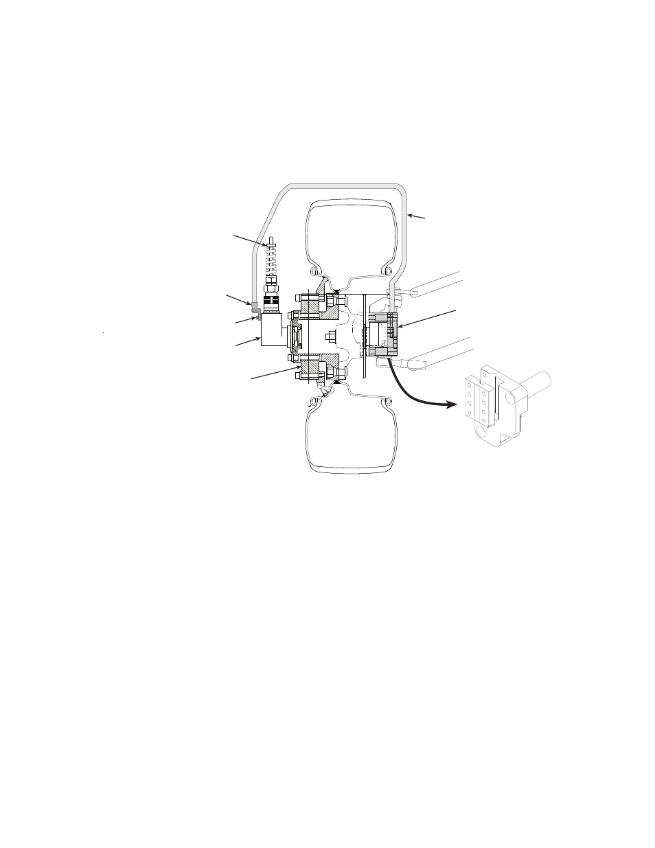
Example Front Anti-rotate Bracket Assembly (view from front)
3. For rear wheel configurations (see the next figure):
A. Attach the anti-rotate bracket in such a way that the end of the anti-
rotate arm is aligned with the pivot point of the swing arm and can
pivot with the swing arm as the ATV jounces while moving or testing.
Torque the four 10-24 UNC fasteners provided to 5.3 N•m (3.9 lbf•ft).
Front Anti-rotate Bracket
This bracket will vary due
to different brake caliper
mounts and spindle design
Anti-rotate bracket to be attached
to unsprung mass or spindle
which will allow the slip ring
to move with the tire as
the ATV is moving or testing
Slip Ring/Encoder
Transducer
Transducer
Output Cable
Anti-rotate and
Hinge Assembly
S10-13
M4 Fasteners (2)