Coordinate system, Transducer interface 32, Coordinate system 24 – MTS SWIFT 10 ATV Sensor User Manual
Page 24
SWIFT 10 ATV Sensors
24
Coordinate System
Hardware Overview
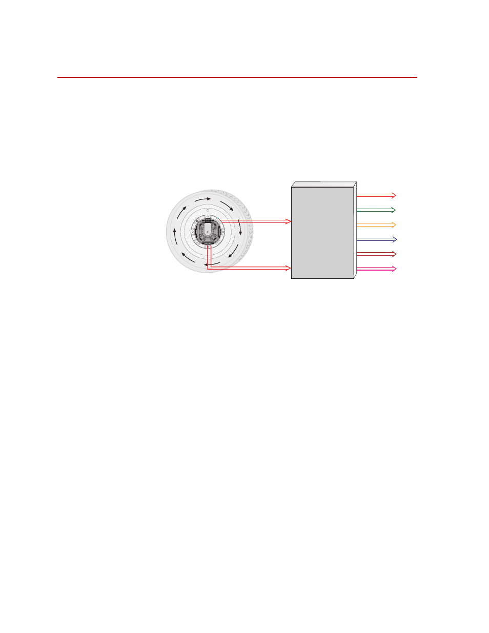
Coordinate System
In the transducer, independent strain gage bridges measure forces and moments
about three orthogonal axes. The signals are amplified to improve the signal-to-
noise ratio. An encoder signal measures angular position, which is used to
convert raw force and moment data from the rotating transducer to a vehicle-
based coordinate system. The force, moment, and encoder information are sent to
the transducer interface (TI).
The TI performs cross talk compensation and converts the rotating force and
moment data to a vehicle coordinate system. The result is six forces and moments
that are measured at the spindle: Fx, Fy, Fz, Mx, My, and Mz. A seventh
(angular) output is available for tire uniformity information, angular position, or
to determine wheel speed (depending on the data acquisition configuration).
Fx
Fy
Fz
Mz
Mx
My
Transducer
Interface
Output signals
±10 Volts
Angular
Position
Bridge
Outputs
S10-10
- Series 111 Accumulator (40 pages)
- Series 249G2 Swivels (34 pages)
- Series 201 Actuators (40 pages)
- Series 215 Rotary Actuator (68 pages)
- Series 242 Actuators (40 pages)
- Series 244 Actuators (68 pages)
- Series 247 Actuators (40 pages)
- Series 248 Actuators (46 pages)
- 709 Alignment System (158 pages)
- Series 609 Alignment Fixture (70 pages)
- 494 Controller Hardware FT 40 (344 pages)
- ReNew Technical Reference (50 pages)
- DCPD Measurement System (46 pages)
- Bionix EnviroBath (40 pages)
- FGW900 High-temperature Furnace (38 pages)
- Model 409.83 Temperature Controller (40 pages)
- Series 651 Environmental Chambers (30 pages)
- Series 653 High-Temperature Furnaces (38 pages)
- Series 658 Environmental Chamber (24 pages)
- Series FEC Environmental Chamber (48 pages)
- Model 685.53 Grip Control Module (24 pages)
- Series 685 Hydraulic Grip Supply (48 pages)
- Bend Fixture-10 kN (2 pages)
- Grip-Manual Bend Fixture-100 kN (2 pages)
- Grip-Manual Bollard-2 kN (2 pages)
- Grip-Manual Bollard-500 N (2 pages)
- Compression Platen-100 kN-100mm (2 pages)
- Compression Platen-100 kN-150mm (2 pages)
- Compression Platen-100 kN-200mm (2 pages)
- Compression Platen-20 kN (2 pages)
- Compression Platen-20 kN-100mm (2 pages)
- Compression Platen-20 kN-200mm (2 pages)
- Compression Platen-20 kN-SST (2 pages)
- Compression Platen-500 N FYC502A (2 pages)
- Compression Platen-500 N FYB502A (2 pages)
- Compression Platen-500 N-50mm (2 pages)
- Grip-Pneumatic Vise-Style-1 kN (2 pages)
- Pneumatic Bollard-500 N (2 pages)
- Scissor-Style-2 kN (2 pages)
- Scissor-Style-5 kN (2 pages)
- Screw-Style-5 kN (2 pages)
- Screw-Style-5 kN-SST (2 pages)
- Bend Fixture-1000 kN (2 pages)
- Bend Fixture-300 kN (2 pages)
- Bolt Grips (32 pages)