Calibration file elements, Items you may edit, Calibration file elements 55 – MTS SWIFT 10 ATV Sensor User Manual
Page 55
Select a Zero Method
SWIFT 10 ATV Sensors
Setting up the Transducer Interface
55
Calibration File Elements
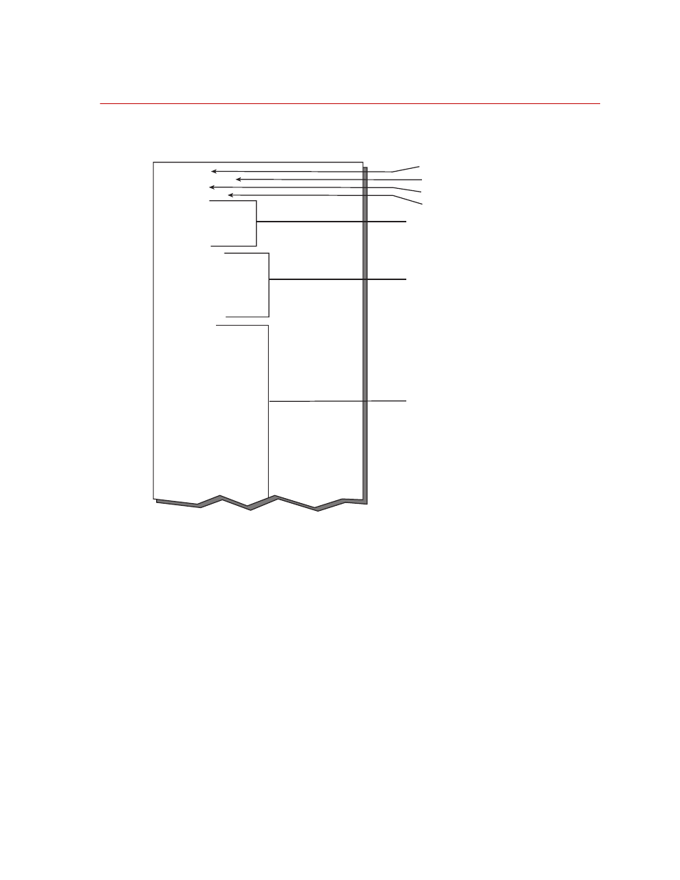
The following figure shows some elements of the calibration file:
Typical Calibration File
Items you may edit
•
OutputPolarities—defines the polarities of the six outputs. Change these
only if your application requires different polarities from those identified on
the transducer label.
•
AngleMode—selects the mode used for determining the encoder sine and
cosine.
•
AngleFixed—used for non-spinning applications.
•
AngleOffset— used for spinning applications. Normally you do not need to
change this value.
•
EncoderSize–defines the size of the encoder.
AngleMode=0
AngleOffset=2.10938
AngleFixed=0
EncoderSize=2048
FXPolarity=0
FYPolarity=0
FZPolarity=0
MXPolarity=1
MYPolarity=0
MZPolarity=1
ZFX1=-0.0249317
ZFX2=0.0181511
ZFY1=0.0692687
ZFY2=-0.275767
ZFY3=0.095961
ZFY4=-0.250816
ZFZ1=-0.042539
ZFZ2=0.00590447
FX1Channel=2
FX2Channel=6
FY1Channel=3
FY2Channel=5
FY3Channel=7
FY4Channel=1
FZ1Channel=4
FZ2Channel=0
InputRange=10.0
KFX1=0.497807
KFX2=0.497807
KFY1=0.478072
KFY2=0.478072
KFY3=0.478072
KFY4=0.478072
KFZ1=0.494473
KFZ2=0.494473
KMX=1.61575
KMYX=1.45028
KMYZ=1.45028
KMZ=1.56116
KFXFY=0.00366337
KFXFZ=-0.00238232
KFXMX 0 0209387
Polarity for each output
(0 = normal, 1 = inverted)
Angle Mode (0 = Spinning, 1 = Fixed)
Angle Offset
Fixed Angle
Bridge Zeroes
Do Not Modify
Calibration Gains
Do Not Modify
S10-33
Encoder Size