1 signal source selection, Digital frequency output parameter setting – Lenze E94AYFLF Digital frequency module User Manual
Page 23
EDS94AYFLF EN 3.2 - 10/2010
L
23
Digital frequency extension module | Parameter setting & configuration
Digital frequency output
Parameter setting
3.2.1
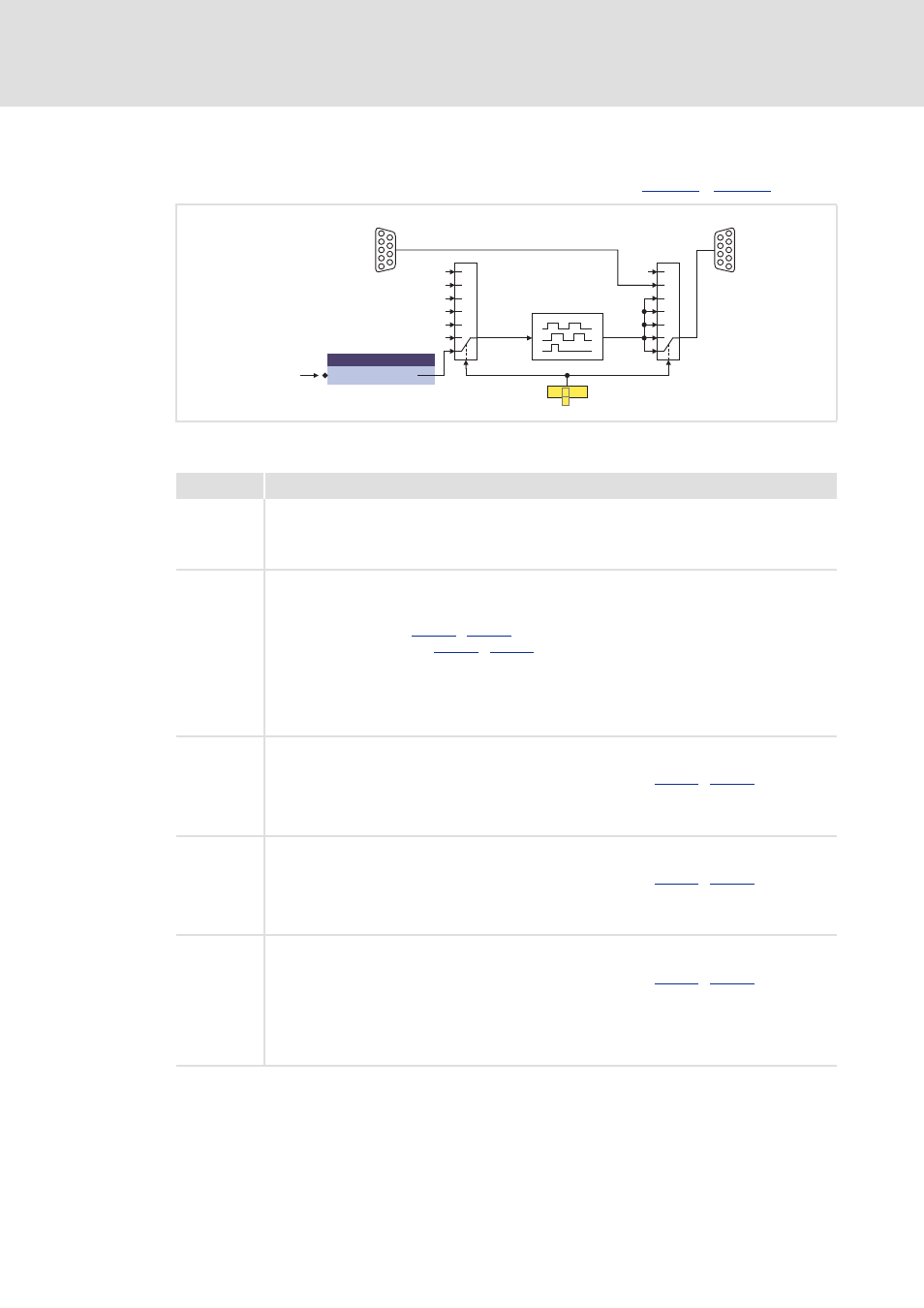
Signal source selection
The signal source for the digital frequency output is selected in
[3-1]
Selection of the signal source for X10
C1 3
4
050
2
1
3
4
5
6
Off
0
Motor speed
Load speed
Resolver speed
Encoder speed
Off
X9
X10
DFIN
DFOUT
7
2
1
3
4
5
6
7
DFOUT_dnSpeedSet_s
LS_DigitalFrequencyOutput
Application
Selection
Info
1
Digital frequency output is inactive
• "0" frequency is output a the digital frequency output.
• All tracks remain on the level output last.
• After the controller is switched on, the tracks A, B, and Z are set to HIGH level.
2
The digital frequency input X9 is directly connected to the digital frequency output.
Note:
Due to the direct connection between input and output, sensors are no longer required.
• The zero pulse offset (
) is without function.
• The frequency limitation (
) is without function.
• The zero track is only output if connected to X9.
• The display parameters for the actual values (speed, frequency, position) are not updated
(remedy: use display parameters of the digital frequency input).
• The outputs DFOUT_dnActualPos_p and DFOUT_dnActualSpeed_s of the system block
LS_DigitalFrequencyOutput are not updated.
3
Output of the motor encoder
• The angle of rotation in [increments] derived from the motor encoder is output as a frequency
signal after being evaluated with the set number of increments (
• The output signal is integrated to a position value via a counter and made available to the
application via the output DFOUT_dnActualPos_p of the system block
LS_DigitalFrequencyOutput.
4
Output of the load encoder
• The angle of rotation in [increments] derived from the load encoder is output as a frequency
signal after being evaluated with the set number of increments (
• The output signal is integrated to a position value via a counter and made available to the
application via the output DFOUT_dnActualPos_p of the system block
LS_DigitalFrequencyOutput.
5
Output of the resolver angle
• The angle of rotation in [increments] derived from the resolver input is output as a frequency
signal after being evaluated with the set number of increments (
• The output signal is integrated to a position value via a counter and made available to the
application via the output DFOUT_dnActualPos_p of the system block
LS_DigitalFrequencyOutput.
• It is irrelevant for the output whether the resolver input is used as a load encoder, motor encoder,
or not used at all for the motor control.