Lenze E94AYFLF Digital frequency module User Manual
Page 19
EDS94AYFLF EN 3.2 - 10/2010
L
19
Digital frequency extension module | Parameter setting & configuration
Digital frequency input
System block "LS_DigitalFrequencyInput"
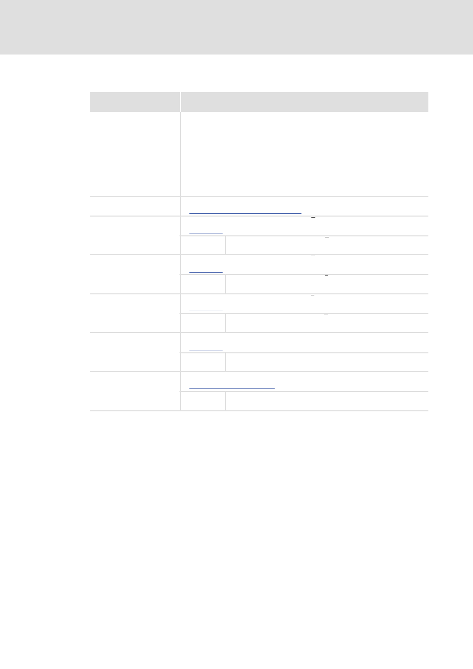
Outputs
Output
Data type
Value/meaning
DFIN_dnActualPos_p
DINT
Current position in [increments]
• Output as signed 32-bit value (positive value ≡ CW rotation).
For software versions prior to V3.0:
• A virtual revolution is resolved to 16 bits.
For software version V3.0 or higher:
• If valid machine parameters are applied to the input DFIN_AxisData, a virtual
revolution is resolved with the encoder resolution specified in the machine
parameters.
• If the input DFIN_AxisData remains unused, a virtual revolution is resolved with
the setting under C00100 (Lenze setting: 16 bits).
DFIN_dnActualSpeed_s
DINT
Current speed in [rpm]
Problem description - speed variations ( 17)
DFIN_bTrackAError
BOOL
Status signal "Differential signal of track A - A invalid"
TRUE The differential signal of track A - A is outside the valid voltage range
(open circuit).
DFIN_bTrackBError
BOOL
Status signal "Differential signal of track B - B invalid"
TRUE The differential signal of track B - B is outside the valid voltage range
(open circuit).
DFIN_bTrackZError
BOOL
Status signal "Differential signal of track Z - Z invalid"
TRUE The differential signal of track Z - Z is outside the valid voltage range
(open circuit).
DFIN_bSense
BOOL
Status signal "Enable/Lamp control signal is set"
TRUE An upstream digital frequency output has set the "Enable signal"
(HIGH signal at X9, pin 8).
DFIN_bVccCtrlLimited
BOOL
Status signal "Voltage control for TTL encoder is at the limit"
Voltage control - TTL encoder ( 14)
TRUE The voltage control for a connected TTL encoder has reached the
limit value.