3 device architecture, Device architecture, 2system and product description – Lenze I/O system 1000 User Manual
Page 9
Lenze · I/O system 1000 · commissioning guidelines for the PLC Designer · DMS 1.2 EN · 11/2012 · TD05
9
2
System and product description
2.3
Device architecture
_ _ _ _ _ _ _ _ _ _ _ _ _ _ _ _ _ _ _ _ _ _ _ _ _ _ _ _ _ _ _ _ _ _ _ _ _ _ _ _ _ _ _ _ _ _ _ _ _ _ _ _ _ _ _ _ _ _ _ _ _ _ _ _
2.3
Device architecture
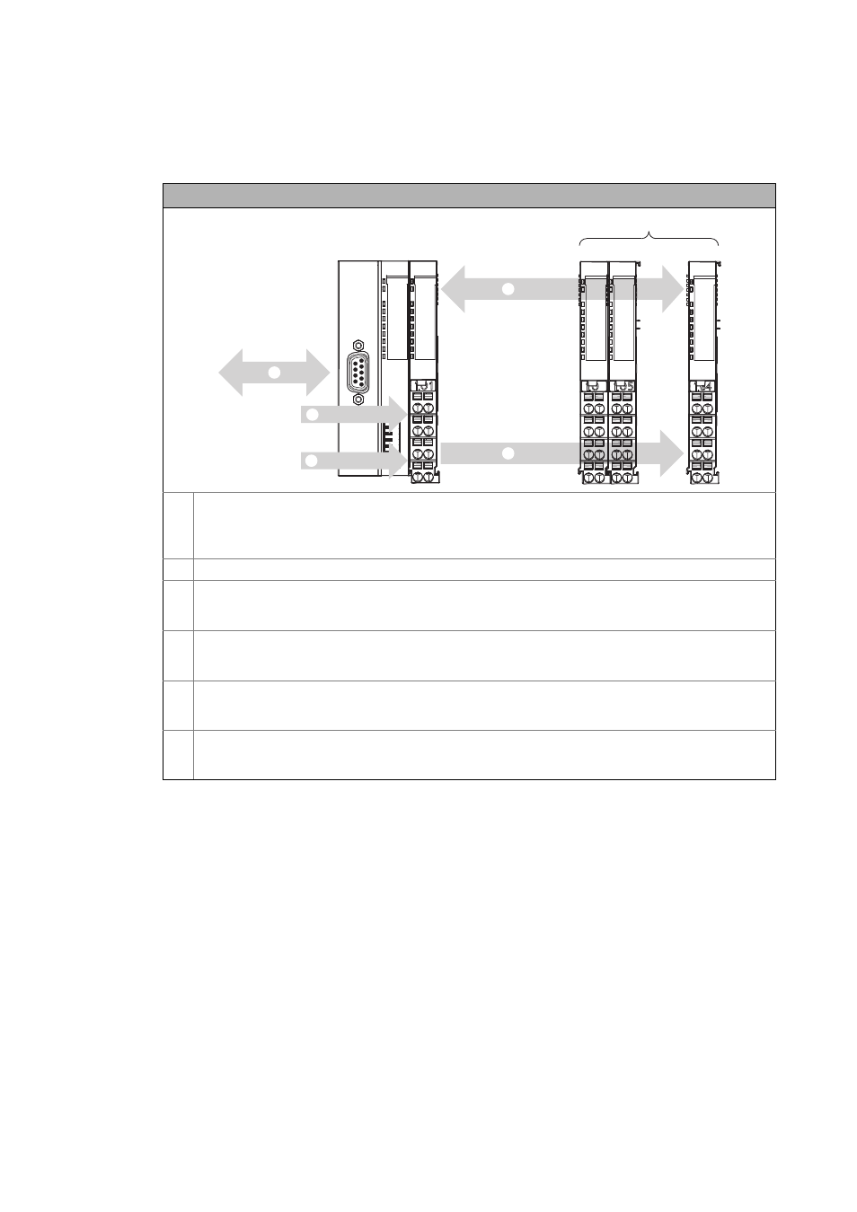
Device architecture of the I/O system 1000
Bus coupler module
• CANopen: EPM-S110
• PROFIBUS: EPM-S120
• EtherCAT: EPM-S130
I/O compound modules, max. 64
n
Connection to the bus system (CANopen/EtherCAT)
• CANopen, PROFIBUS: via a 9-pole Sub-D plug (see illustration)
• EtherCAT: RJ45, double
o
Internal backplane bus for communication between the bus coupler module and the I/O compound modules
• Side-by-side mounting of the module feet of the I/O compound modules provides for the electrical
connection to the bus coupler module.
p
Supply voltage DC 24 V, max. 10 A for consumers at output modules
• Side-by-side mounting of the module feet of the I/O compound modules provides for the electrical
connection to the bus coupler module.
q
Supply voltage DC 24 V for the electronics
• Side-by-side mounting of the module feet of the I/O compound modules provides for the electrical
connection to the bus coupler module.
0
64
... ...
4
1