Electrical installation, Z1 z2 zx rb1, Rb x – Lenze EMB9352−C User Manual
Page 98
Electrical installation
General requirements
Permissible cable lengths
l
98
EDBMB935X DE/EN/FR 13.0
+UG
-UG
A1
E
A
E
A
E
A
Z1
Z2
Zx
RB1
L
8m
3
1
£
2
RB2
L
8m
3
2
£
RB
x
L
8m
3x
£
L
11
L
0
L
13
L
2 m
21
£
L+
L
2
m
0
11
£
L+
L
2
m
0
12
£
L+
L
2
m
0
1
x
£
L
2 m
2x
£
L
12
2
2
2
2
2
2
9350br_005
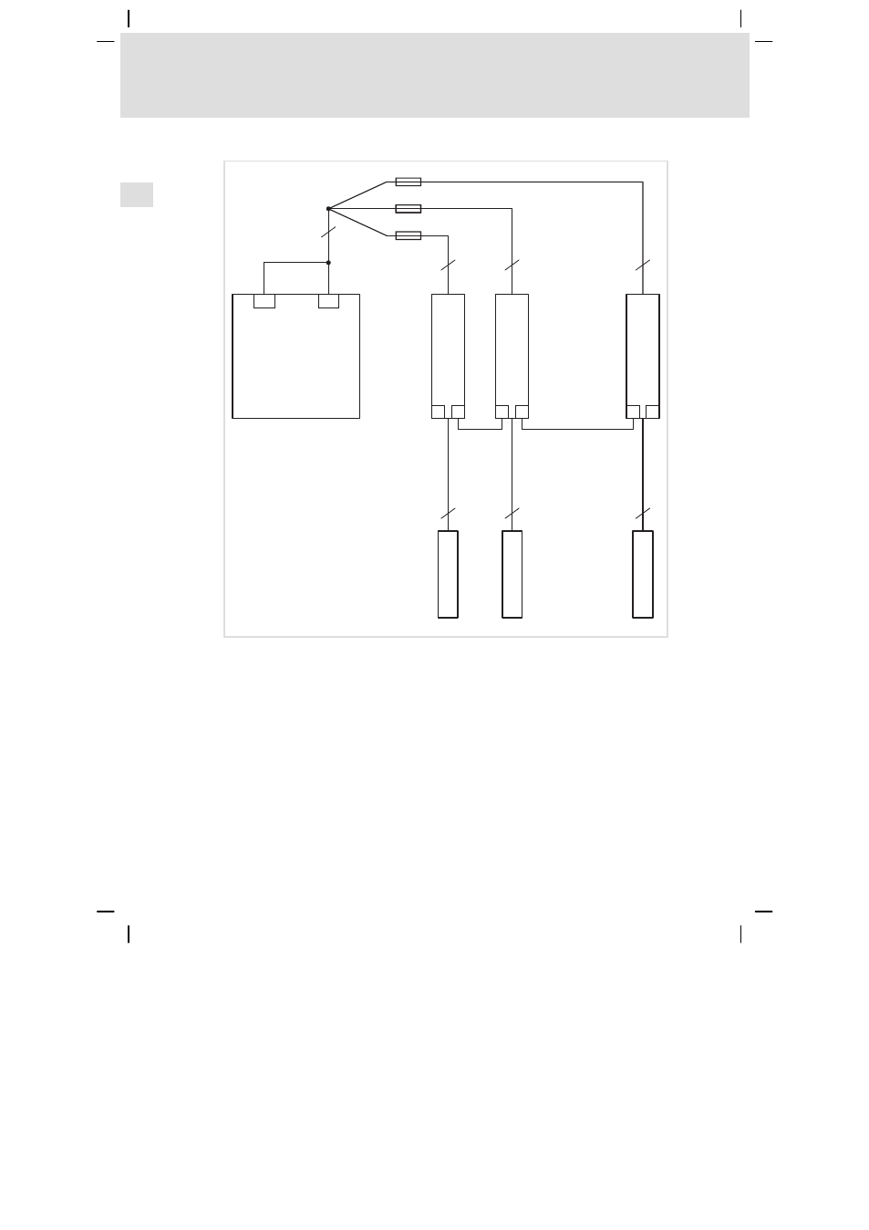
Fig. 10
Example circuit for parallel operation
A1
Controller
Z1
Brake chopper 1 = master
Z2 ... Zx
Brake chopper 2 ... x = slave 2 ... slave x
RB1, RB2, RBx
External brake resistors
L0
Cable length of controller Ċ collection point
L1x
Cable length of collection point Ċ braking unit
L2x
Cable length of synchronisation cable for parallel operation
L3x
Cable length of brake chopper Ċ brake resistor