Conditioner reel installation, Figure 3-24: conditioner reel arm stop, Warning – Landoll 7450 VT Plus User Manual
Page 43
ASSEMBLY INSTRUCTIONS
3-25
Conditioner Reel Installation
1.
Assemble 1 x 8 adjustment bolt through adjustment
pin on frame, 1" lock washer, (2) 1-8 hex nuts, and
17" heavy spring assembly. On the outer wings,
remove one snap ring and slide large slot of reel arm
stop over adjustment pin. Replace snap ring before
installing the 1 x 8 adjustment bolt. The reel arm stop
will be in between the plates welded to the frame, but
mounted to the outer end of the reel.
2.
Install 1-1/2” flange bearing into reel arm. Slide in
1-1/2” pivot bushing.
3.
Attach reel arm to upper hole on rear center or wing
frame or double mount using 1-8 x 6-1/2 hex head
cap screw and hex lock nut.
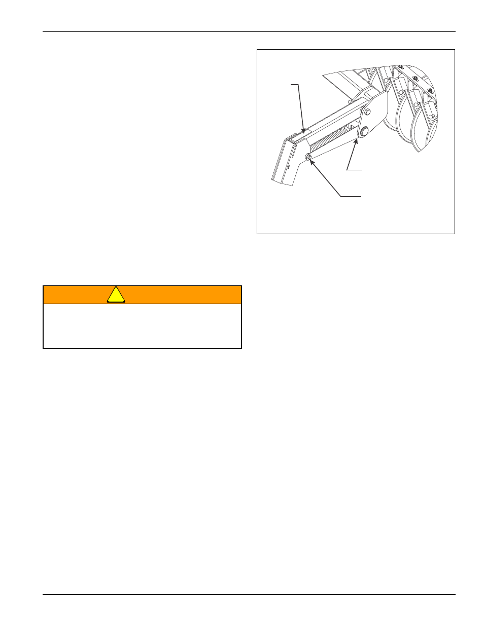
4.
Assemble 17" heavy spring assembly to reel arm
using 1" pivot pin, and 5/16 x 1-1/2” spring slotted
pins. Set pin centers to 21” dimension as shown in
(Figure 3-23). On the outer wings, the reel arm stop
will replace the machinery bushing on the outside of
the reel arm (See Figure 3-24.) This will prevent the
outer reels from hanging down so far while the
machine is being folded. Refer to pages 2-4 thru 2-9
for reel arm stop locations.
WARNING
5.
Attach reel/gang bar assembly to reel arms using
gang bar mount plate, 3/4-10 x 6 hex head cap
screws and double hex lock nuts. Refer to pages 2-4
thru 2-9 for reel gang bar placement locations.
6.
Attach yellow reflector decals on outer arms (See
Figure 3-30.) The decals are located in the manual
tube. Reflector decal locations also shown on pages
2-4 thru 2-9.
Figure 3-24: Conditioner Reel Arm Stop
Do not attempt to lift heavy parts (such as the
frame, disc gangs, lift, pull hitch, or reel/gang bar
assembly manually. Use a hoist or a forklift to
move these parts into position.
REEL ARM STOP
TO INSIDE
NOTE: DO NOT USE
MACHINE BUSHING
HERE
7450 reel arm stop
YELLOW
REFLECTOR
DECAL