Hydraulic installation, Caution – Landoll 7450 VT Plus User Manual
Page 39
ASSEMBLY INSTRUCTIONS
3-21
Hydraulic Installation
NOTE
See Figures 3-11 through 3-16 for hydraulic cylinder
fittings (factory installed and those installed during
setup).
Refer to Figures 3-11- 3-12 for lift and fold hydraulic
diagrams for 7450-39' model.
Refer to Figures 3-13- 3-14 for lift and fold hydraulic
diagrams for 7450-44' model.
Refer to Figures 3-15 - 3-16 for lift and fold hydraulic
diagrams for 7450-49' model.
Refer to Figure 3-17 for transport lock hydraulic
diagram, front and rear manifold drawings, and fold
cylinder detail for all models.
1.
Attach the base end of the 4 x 30 (7450-39’/
7450-44’) or 4-1/2 x 30 (7450-49’) fold cylinder to the
fold cylinders mounts on the center frame with the
pins and roll pins as designated in Figure 3-18.
Position the cylinders so the hydraulic ports point to
rear on front and to front on the rear and toward the
center of machine.
2.
Using a 1-1/4 x 6-1/8 fold pin, flat washers, and 5/16
x 2-1/2 roll pins, attach the rod end of the 4” x 30”
cylinders to the slotted mounts on the inner wing
frames (See Figure 3-18.)
3.
Using 1-1/4 x 6-1/8 fold pin (7450-39’) or pins
provided with cylinder (7450-44’/7450-49’), attach
base of outer wing fold cylinder to mount on inner
wing.
4.
Using a 1-1/4 x 9-9/16 fold pin, flat washers, wing
fold rollers, wing fold spacers, and 5/16 x 2-1/2 roll
pins, attach the rod end of the 4” x 30” cylinders to
the fold links on the double hinge (See Figure 3-18.)
NOTE
Rod ends of fold cylinders need to be left unassembled
until fold hydraulic system is fully charged with oil to
prevent machine damage.
5.
Install 90 degree regular adapter fittings in both ends
of all lift cylinders and transport lock cylinders (4-1/2
x 16, 4 x 16, 3-3/4 x 16, 3-1/2 x 8, and 3-1/4 x 8).
CAUTION
6.
Install the 16 port front manifold to the manifold
bracket on the front of the center frame using 1/2-13
x 3-1/2 hex head cap screws and hex lock nuts.
7.
Attach the 8 port manifold to the rear manifold
bracket on the implement using 1/2-13 x 3-1/2 hex
head cap screws and hex lock nuts.Install lift system
hoses per Figures 3-11 and 3-15. Wrap lift system
hoses with blue hose wrap.
8.
Attach hose clamp brackets to the scraper bar (See
Figure 3-19.) Secure hoses to the brackets with
hose clamps, 3/8-16 x 1-3/4 hex head cap screws,
and hex lock nuts.
9.
Install fold system hoses per Figures 3-12 and 3-16.
Wrap fold system hoses with yellow hose wrap.
10. Install 1/32” restrictors, (2) 290” hoses, and couplers
in the hydraulic leveler. Wrap hydraulic leveler hoses
with black hose wrap.
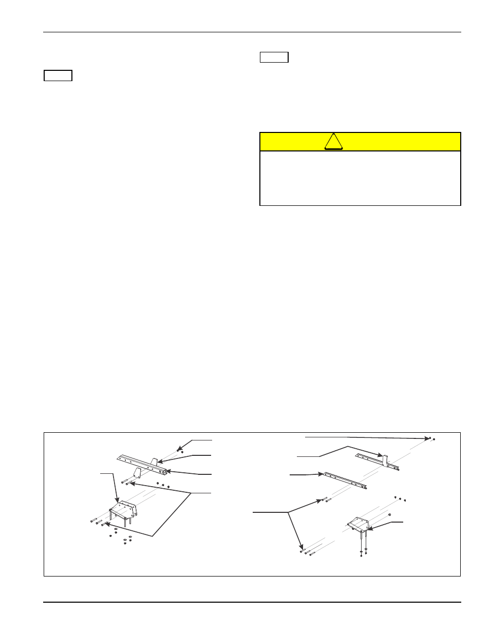
11. Attach outer wing stops and wing stabilizer to fold
stabilizer mount using 3/4-10 x 5 hex head cap
screws and hex lock nuts (See Figure 3-20.)
Figure 3-20: Wing Stabilizer Bracket Mounting Installation
1/16” Restrictors are installed in the rod end of
wing fold cylinders to prevent uncontrolled
dropping of wings. Removal of these restrictors,
or improper installation can result in serious
damage to the implement.
7450-39 AND -44 MODELS
3/4-10 HEX LOCK NUT
OUTER WING STOP
3/4-10 X 5 HEX
HEAD CAP
SCREW
WING STABILIZER
7450-49 MODEL
FOLD
STABILIZER
MOUNT
INSTALLED
AT LANDOLL
FOLD
STABILIZER
MOUNT
INSTALLED
AT LANDOLL