Landoll PFT Floating Ring Pulverizer User Manual
Page 13
298rev401
5K089
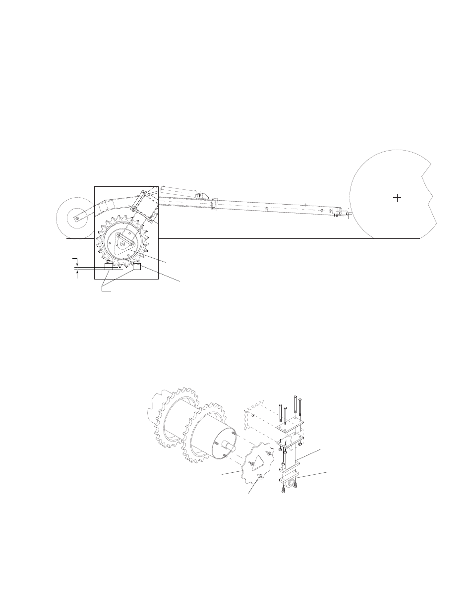
ROLLERS
ON BLOCKS
PARKED
TRACTOR
WITH
LOCKED
BRAKES
PILLOW BLOCK BEARING
DRUM CONTACTING ROLLERS
FIGURE 8
PILLOW BLOCK
BEARING
BEARING SUP-
PORT
RETAINER PLATE
LOCK NUTS 5/8
FIGURE 9
2
Page 11
REPLACING OR ADDING ROLLER WHEELS
Although the packer wheels are manufactured from high grade ductile iron, wear or breakage may
require that some wheels be periodically replaced. Follow these steps when replacing wheels.
1. Attach a tractor to the pulverizer, put the tractor transmission into PARK, and lock the brakes on
the tractor. Hydraulically raise the pulverizer to the transport position and insert the transport
pin. With the pulverizer in the transport position, slide all the wheels toward one end of the
drum. Remove the transport pin and lower the machine so that the packer wheels rest on
blocks approximately two inches off the ground (see figure 8). Continue to lower the machine till
the outside of the roller drum contacts the bottom ring of the packer wheels.
2. Remove the pillow block bearing and the bearing support from the end of the drum to which you
will be adding wheels. The pillow block bearing is secured to the drum shaft by means of an
eccentric locking collar. Loosen the set screws which tighten the collar to the shaft. Then with a
punch, rotate the collar in the direction opposite which the shaft turns in normal operation. Next
remove the nuts from the bolts which mount the bearing supports to the frame and slide the
bearing and the support off the shaft. Remove the three 5/8" lock nuts which attach the retainer
plate to the drum and remove the plate.
3. Slide the replacement wheels onto the drum, replace the retainer and tighten the lock nuts to
150 ft.-lb. Slide the pillow block bearing and bearing support onto the shaft until the bearing
bottoms against the shaft shoulder. Replace the bolts which mount the bearing support to the
frame and tighten the lock nuts to 150 ft.-lb. Now take a punch and rotate the locking collar of
the bearing in the direction which the bearing will rotate and tighten the set screw against the shaft.