Electrical control console schematic, Electrical control console schematic -33 – Kinze 3600 Lift and Rotate Planter (70 CM) Rev. 5/14 User Manual
Page 137
TM
Model 3600
M0249-01
12/12
6-33
Lubrication and Maintenance
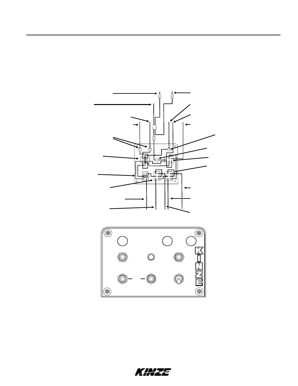
ELECTRICAL CONTROL CONSOLE SCHEMATIC
NOTE: Disconnect control console from tractor battery before doing any electrical work. Keep wiring
harnesses away from high temperature areas or sharp edges. DO NOT route wiring harnesses along battery
cables. Use cable ties to keep wire harness away from moving parts on tractor and planter. Be sure tractor
frame ground connections are clean to provide good electrical contact.
NOTE 1. Operating marker or point row switch in either direction lights panel light.
NOTE 2. Point row clutch switch operates independently from rest of control box.
NOTE 3. Power to marker switch is fed through auxiliary switch and two transport function switches.
Operating any switch in lower row disables marker function and turns off panel light. (If point row clutch
switch is OFF.)
See electrical control console schematic and wiring harness at two-speed point row clutch solenoids for planter
equipped with optional Two-Speed Point Row Clutch Package in this section.
Pin “H” BLUE (L.H. Marker)
Pin “O” RED (R.H. Marker)
Main Fuse (15A)
Indicator Light
Marker Switch
Raise/Wing Lock Switch
Pin “F” YELLOW/RED
Pin “V” BLUE/BLACK
(Raise To Transport)
Pin “A” ORANGE/RED
(Tongue)
Pin “C” BLACK/RED (Ground)
Pin “T” BLACK (Ground)
BLACK (- 12 VDC)
RED (+ 12 VDC)
Pin “B” BLUE/RED (Rotate)
Pin “W” ORANGE/BLACK (Auxiliary)
Pin “R” BROWN (L.H. Point Row Clutch)
Pin “G” ORANGE (R.H. Point Row Clutch)
Delay Action Fuse (10A)
Point Row Clutch
Switch
Auxiliary Switch
Rotate/Tongue Switch
MAIN
FUSE
15A
USE 10 AMP
DELAY
ACTION
ONLY
POINT ROW
OFF
LEFT
ON
OFF
AUXILIARY
ROTATE
TONGUE
OFF
RIGHT
LEFT
MARKER
OFF
WING LOCK
RAISE
MARKERS WILL NOT FUNCTION WITH AUXILIARY SWITCH ON
RIGHT
fi