Hydraulic schematic - vacuum fan motor system, Hydraulic schematic - vacuum fan motor system -47, And oil cooler system -47 – Kinze 3600 Lift and Rotate Planter Rev. 7/14 User Manual
Page 155
TM
Model 3600
M0236-01
Rev. 7/11
6-47
Lubrication and Maintenance
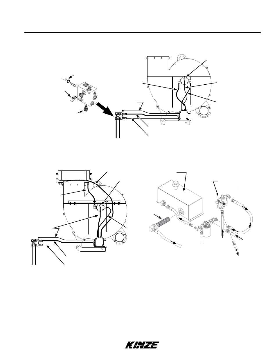
HYDRAULIC SCHEMATIC - VACUUM fAN MOTOR SYSTEM
NOTICE
failure to connect to a return with zero pressure will damage hydraulic
motor. Connect hydraulic motor case drain to a case drain return line
with zero pressure on tractor. DO NOT connect hydraulic motor case
drain to SCV outlet. Contact tractor manufacturer for specific details
on “zero pressure return”.
HYDRAULIC SCHEMATIC - OPTIONAL TRACTOR DRIVEN PTO PUMP AND OIL COOLER
SYSTEM
Fan motor assembly
Vaccum fan motor
valve block assembly
Case drain
(⅜" hose)
Pressure (½" hose)
Return (⅝" hose)
Case drain
Pressure
Return
Drain hose
Relief valve
Check valve
Oil cooler
Fan motor
assembly
Pressure
Return (⅝" hose)
Return (⅝" hose)
Case drain
(⅜" hose)
Pressure (½" hose)
Return (⅝" hose)
Strainer
Oil reservoir
EX
CF
IN
To PT
O pump
Flow control valve
From PT
O pump
Case
drain
Motor
return
Motor pressure
Filter