41 lubrication and maintenance – Kinze 3600 Lift and Rotate Planter Rev. 7/14 User Manual
Page 149
TM
Model 3600
M0236-01
Rev. 7/11
6-41
Lubrication and Maintenance
NOTE:
1. Point row and reduced
rate clutch switches operate
independently from rest of
control console.
2. Marker switch power is fed
through auxiliary switch and
two transport function switches.
Operating any switches in lower
row disables marker function
and turns marker panel light off.
NOTE: Disconnect control
console from tractor battery
before doing any electrical
work. Keep wiring harnesses
away from high temperature
areas or sharp edges. DO NOT
route the wiring harnesses
along battery cables. Use tie
straps to keep wire harness
away from moving parts on
tractor and planter. Be sure
ground connections to tractor
frame are clean to provide good
electrical contact.
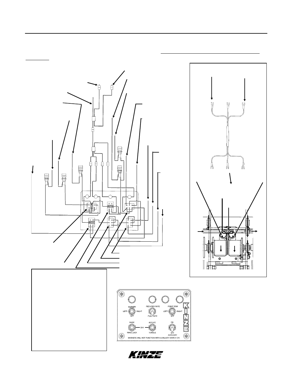
ELECTRICAL CONTROL CONSOLE SCHEMATIC (With Optional Two-Speed Point Row
Clutches) AND WIRING HARNESS AT TWO-SPEED POINT ROW CLUTCH SOLENOIDS
Pin “T” BLACK (Ground)
Pin “S” YELLOW
(L.H. Two-Speed Clutch)
Pin “U” RED/BLACK
(R.H. Two-Speed Clutch)
Pin “H” BLUE
(L.H. Marker)
Pin “O” RED
(R.H. Marker)
Pin “F”
YELLOW/RED
(Wing Lock)
Pin “V”
BLUE/BLACK
(Raise)
Pin “A”
ORANGE/RED
(Tongue)
Pin “B”
BLUE/RED
(Rotate)
Pin “C” BLACK/RED (Ground)
BLACK (- 12
VDC)
RED (+ 12 VDC)
Pin “R” BROWN
(L.H. Point Row Clutch)
Pin “G” ORANGE
(R.H. Point
Row Clutch)
Pin “W”
ORANGE/
BLACK
(Auxiliary)
Point Row
Clutch Switch
Auxiliary Switch
Raise/Wing Lock Switch
Marker Switch
Rotate/Tongue Switch
Reduced Rate Clutch Switch
BLUE -
L.H. To Yellow
R.H. To Red/Black
Input
BLACK Ground Wire
Connects To One
Terminal
Output
RED - Point Row
Clutch Solenoid
RED -
L.H. To Brown
R.H. To Orange
BLUE - Reduced
Rate Clutch Solenoid
BLACK -
To Ground
Clamp
Jumper Wire
L.H. SIDE SHOWN