Valve block - located on rear center frame, Valve block - located on rear center frame -40 – Kinze 3600 Lift and Rotate Planter Rev. 7/14 User Manual
Page 148
M0236-01
Model 3600
6-40
Rev. 7/11
TM
Lubrication and Maintenance
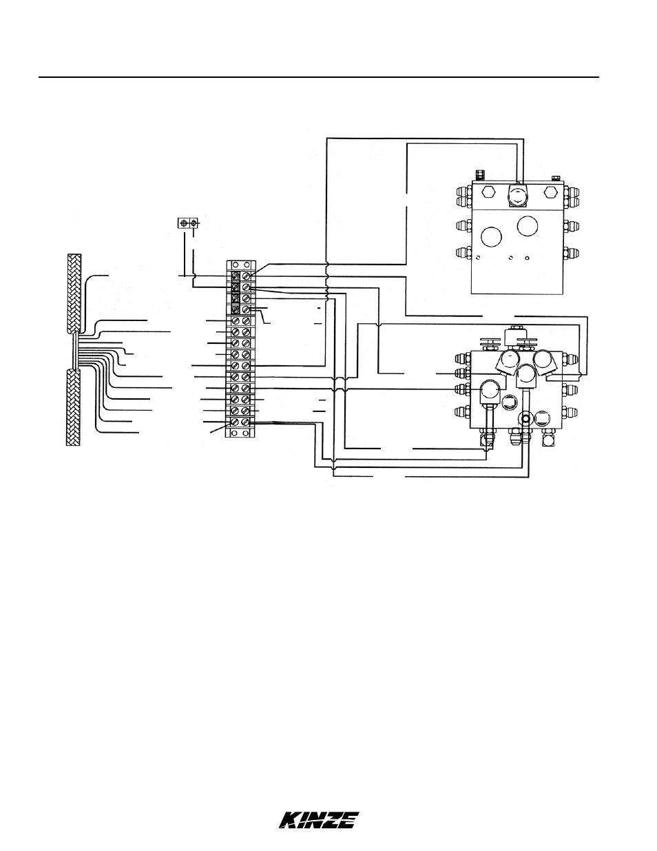
VALVE BLOCK - LOCATED ON REAR CENTER fRAME
1. BLACK - Pin “T” (Ground)
2. RED/BLACK - Pin “U” (R.H. Two-Speed Clutch)*
3. YELLOW - Pin “S” (Le.H.Two-Speed Clutch)*
4. ORANGE/BLACK - Pin “W” (Auxiliary) - Ports V5 & V6
5. ORANGE/BLACK - Pin “W” (Auxiliary) - Ports V5 & V6
6. BLUE/BLACK - Pin “V” (Raise To Transport) - Port V16
7. RED - Pin “O” (R.H. Marker) - Port V1
8. BLUE - Pin “H” (L.H. Marker) - Port V2
9. ORANGE - Pin “G” (R.H. Point Row Clutch)
10. BROWN - Pin “R” (L.H. Point Row Clutch)
11. YELLOW/RED - Pin “F” (Wing Lock) - Ports V3 & V4
12. YELLOW/RED - Pin “F” (Wing Lock) - Ports V3 & V4
13. BLACK - (R.H. Point Row Ground)
14. BLACK - (L.H. Point Row Ground)
15. RED - (R.H. Point Row)
16. RED - (L.H. Point Row)
* See page 7-40 if equipped with optional Two-Speed Point Row Clutch Package.
V17
Ground clamp
attached to
planter frame
V15
V16
V7
V8
V2
V1
V3
P2
V5
V6
P1
V4
15.RED
16. RED
13. BLACK
Ground
14. BLACK
Ground
Terminal
strip
TOP VIEW
REAR VIEW
1. BLACK Ground
2. RED/BLACK
4. ORANGE/BLACK
5. ORANGE/BLACK
6. BLUE/BLACK
12. YELLOW/RED
11. YELLOW/RED
3. YELLOW
9. ORANGE
10. BROWN
8. BLUE
7. RED
Ground
Ground
Ground
Ground
Ground