Lubrication and maintenance, Hydraulic system schematic, Rev. 7/11 – Kinze 3600 Lift and Rotate Planter Rev. 7/14 User Manual
Page 152: L.h. row marker cylinder, R.h. wing lift cylinder(s) slave
M0236-01
Model 3600
6-44
Rev. 7/11
TM
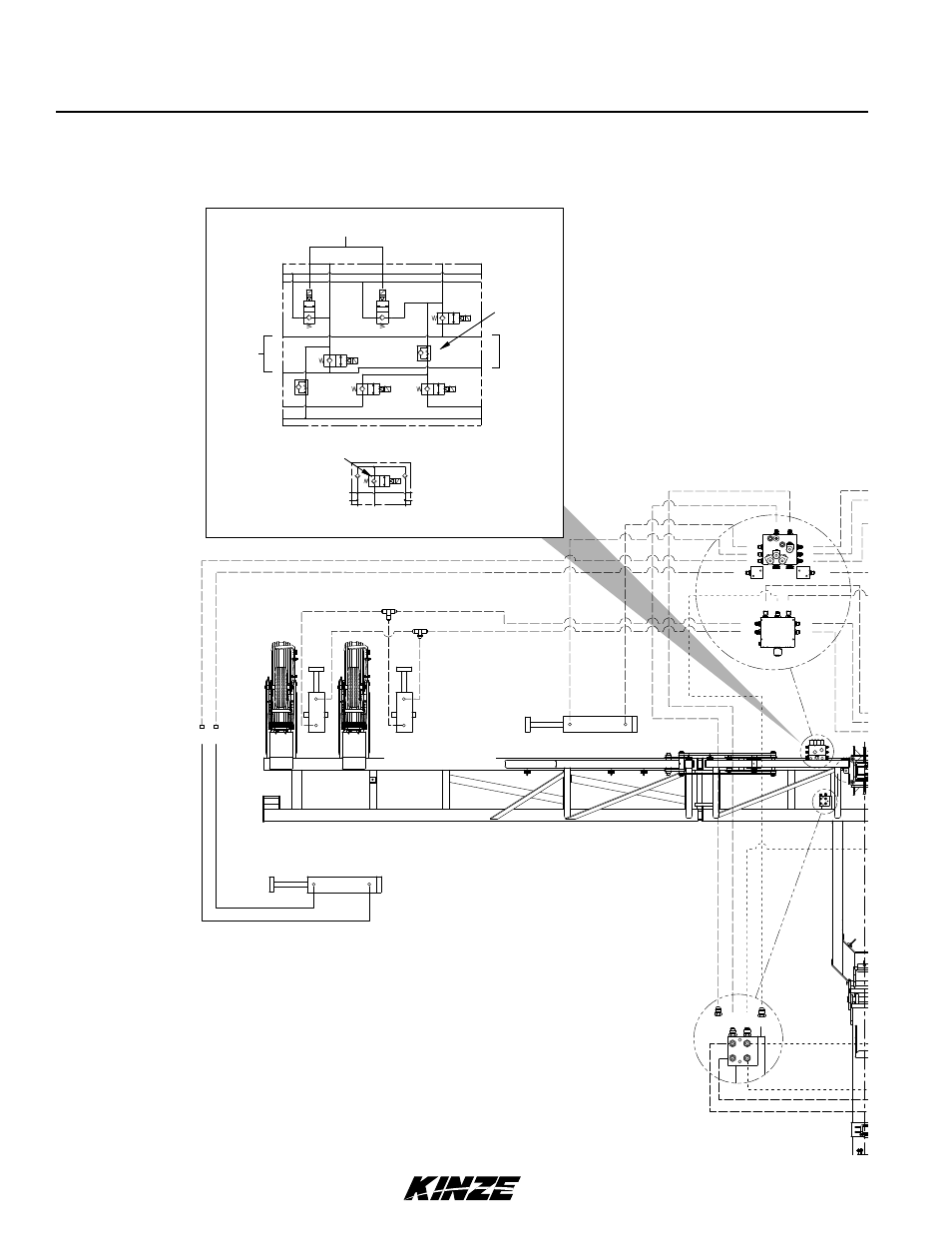
Lubrication and Maintenance
C2
D4
D2
C1
D3
D5
C3
V8
B8
B6
A6
B4
A4
A9
B9
B7
A7
B5
V7
A5
V3
V6
V5
V4
A8
V2
V1
A1
B1
L.H. Marker
R.H. Wing Lift Cylinder
Raise Solenoid
Front Center Lift Cylinder
Rear Center Lift Cylinder
L.H. Wing Lift Cylinder
Auxiliary
L.H. Wing Lock
Cylinder
Marker Speed
Lower
R.H. Wing
Lock Cylinder
R.H. Marker
A4
R.H. Wing Lock Cylinder
C3
A6
Center Lift Cylinder
REAR L.H. Master
D5
C3
C1
D3
D2
D4
C2
D2
B1
B4
B6
A6
A1
B5
B7
A7
LH
D1
L.H. Row Marker Cylinder
Hose Support / Junction - Located on L.H. Side of Center Pivot.
See “Hydraulic Hoses and Fittings on Hitch”
Valve Block - Located on
R.H. Rear Center Frame
Junction Block - Located on
R.H. Side of Center Pivot
B5
Center Lift Cylinder
FRONT R.H. Master
L.H. Wing Lock Cylinder
A7
B7
D4
C2
B4
A5
B6
D5
D3
D1
RH
A1
C1
D1
A1
B1
C1
B1
D1
D1
B1
C1 A1
D4
C2
C3
D5
R.H. Row Marker Cylinder
R.H. Wing Lift
Cylinder(s) SLAVE
L.H. Wing Lift
Cylinder(s) SLAVE
Hydraulic System Schematic
12 Row (One Wing Lift Cylinder Per Wing) and 16 Row Shown (Two Wing Lift Cylinders Per Wing)