7 technical data – JUMO 709040 TYA-110 thyristor power unit Operating Manual User Manual
Page 52
7 Technical data
52
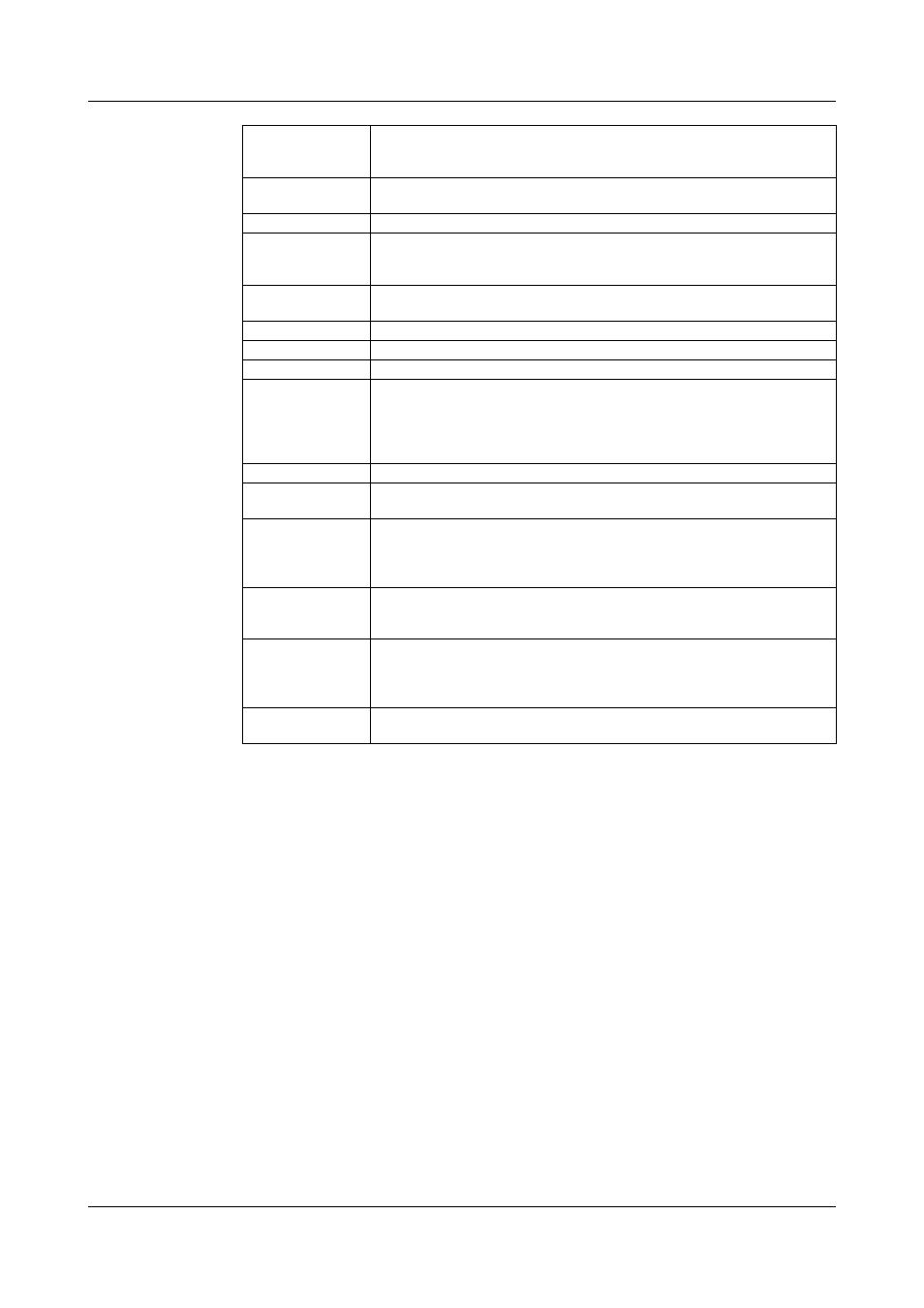
Actual (power) output
V
2
signal as standard.
With extra code TR or TO: free choice between V
2
, P, or I
2
signal via internal
switches, adjustable from 0 — 5V to 0 — 10V. I
max
≈ 2mA.
Electrical connection Control wiring by screw terminals for conductor cross-sections 0.2 — 2.5mm
2
.
Load connections by cable lugs to DIN 46 212.
Protection
IP00 as per EN 60 529, heatsink is grounded
Permitted ambient
temperature range
0 — 45°C
Permitted current derated by 2% for each °C increase in ambient temperature;
the maximum permissible ambient temperature must not exceed 60°C.
Permitted storage
temperature range
-10 to +70°C
Climatic conditions
rel. humidity
≤ 75% annual mean, no condensation
Cooling
natural convection
Operating position
vertical
Operating conditions
The thyristor power unit is designed as a built-in unit to:
VDE 0160 5.5.1.3 (5/88)
VDE 0106 Part 100 (3/83)
pollution degree 2 to VDE 0110 Part 1 4.2 (1/89)
overvoltage category Ü III to VDE 0160 5.7 (5/88)
Test voltage
to VDE 0160 Table 4 (6/88)
Electromagnetic
compatibility
Control electronics to EN 61 326
Creepage distance
control electronics to load circuit
≥ 10mm
control electronics to housing
≥ 10mm
Unit can be connected to SELV circuits.
SELV = Seperate Extra Low Voltage
Housing
TYA110/3,
25 (50)
110 x 195 x 152mm
TYA110/3,
75 (100)
125 x 195 x 170mm
TYA110/3, 150
(250)
150 x 220 x 280mm
Weight
TYA110/3,
25 (50)
2.8 kg
TYA110/3,
75 (100)
3.7 kg
TYA110/3, 150
8.6
kg
TYA110/3
250
9.0 kg
Standard
accessories
1 mounting plate for wall-mounting
1 Operating Instructions B 70.9040